Subaru Crosstrek Service Manual: Removal
CONTROL SYSTEMS > Select Cable
REMOVAL
1. Shift the select lever to “N” range.
2. Disconnect the ground cable from battery. NOTE">
NOTE:
For model with battery sensor, disconnect the ground terminal from battery sensor.
3. Lift up the vehicle.
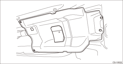
4. Remove the center exhaust pipe. Center Exhaust Pipe > REMOVAL">
5. Remove the center exhaust cover.
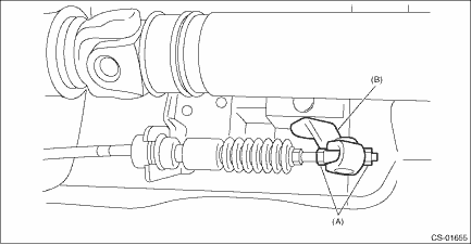
6. Remove the snap pin and washer from the shifter arm.
CAUTION:
Do not apply extra overload while holding the part (A).
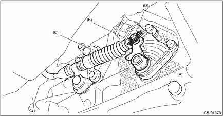
(A) | Shifter arm |
(B) | Snap pin |
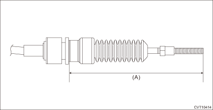
(C) | Select cable |
(D) | Washer |
7. Remove the plate assembly from the transmission case.
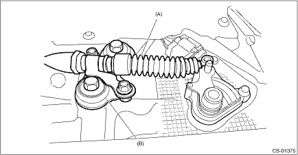
(A) | Select cable |
(B) | Plate ASSY |
8. Disconnect the cable from arm COMPL.
CAUTION:
Do not apply extra overload while holding the part (A).
(A) | Adjusting nut |
(B) | Arm COMPL |
9. Raise the claw of clamp to remove the cable from bracket.
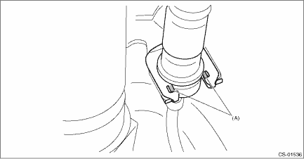
(A) | Claw |
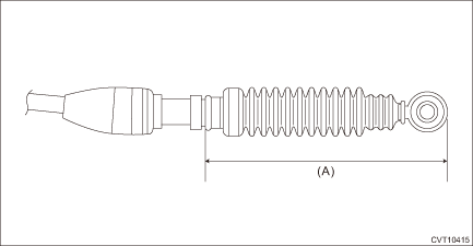
10. Remove the select cable from plate assembly.
 Adjustment
CONTROL SYSTEMS > Select CableADJUSTMENT1. Shift the select lever to “N” range.2. Lift up the vehicle.3. Remove the center exhaust pipe. Center Exhaust Pipe > REMOVAL">4. Re ...
 Inspection
CONTROL SYSTEMS > Select CableINSPECTIONCheck the removed cable and replace or adjust if damaged, rusty or malfunctioning.1. Check the cable for smooth operation.2. Check the inner cable for damage ...
Other materials:
Removal
INTAKE (INDUCTION)(H4DO) > Air Cleaner CaseREMOVAL1. Disconnect the ground cable from battery. NOTE">2. Remove the air intake duct. Air Intake Duct > REMOVAL">3. Disconnect the connector (A) from the mass air flow and intake air temperature sensor, and remove the clip (B).4. ...
Dtc p2530 ignition switch run position circuit
ENGINE (DIAGNOSTICS)(H4DO) > Diagnostic Procedure with Diagnostic Trouble Code (DTC)DTC P2530 IGNITION SWITCH RUN POSITION CIRCUITDTC detecting condition:Immediately at fault recognitionTrouble symptom:Improper idlingCAUTION:After servicing or replacing faulty parts, perform Clear Memory Mode Cl ...
Screen OFF setting
1. Perform the preparation steps according
to "Preparation for image quality and
volume settings"
2. Operate the "
" or "
" switch to
select the "Screen Off" item. Then push
the
button.
3. Push the
button once more.
4. The screen is turned off.
Restoring the s ...
