Subaru Crosstrek Service Manual: Dtc p2530 ignition switch run position circuit
ENGINE (DIAGNOSTICS)(H4DO) > Diagnostic Procedure with Diagnostic Trouble Code (DTC)
DTC P2530 IGNITION SWITCH RUN POSITION CIRCUIT
DTC detecting condition:
Immediately at fault recognition
Trouble symptom:
Improper idling
CAUTION:
After servicing or replacing faulty parts, perform Clear Memory Mode Clear Memory Mode > OPERATION"> , and Inspection Mode Inspection Mode > PROCEDURE">.
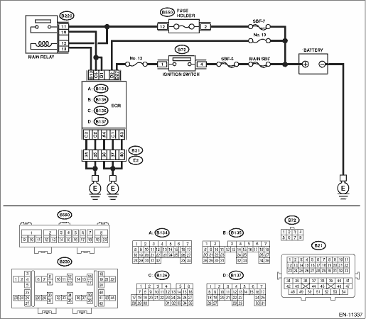
Wiring diagram:
Engine electrical system Engine Electrical System">
| STEP | CHECK | YES | NO |
1.CHECK ECM CONNECTOR.
Check the connecting condition of ECM connector.
Is the ECM connector correctly connected?
Diagnostic Procedure with Diagnostic Trouble Code (DTC) > DTC P2530 IGNITION SWITCH RUN POSITION CIRCUIT">Go to Step 2.
Connect the ECM connector correctly.
2.CHECK INPUT VOLTAGE OF ECM.
1) Turn the ignition switch to ON.
2) Measure the voltage between ECM connector and engine ground while wiggling the harness between ECM connector and F/B connector.
Connector & terminal
(B137) No. 2 (+) — Engine ground (−):
Is the voltage 8 V or more all the time?
Even if DTC is detected, the circuit has returned to a normal condition at this time. Reproduce the failure, and then perform the diagnosis again.
NOTE:
In this case, the following items may be the cause of fault.
• Open circuit or short circuit to ground in harness between ECM connector and F/B connector
• Poor contact of fuse (F/B No. 5)
• Poor contact of IG2 relay connector
• Poor contact of IG2 relay
Repair the harness and connector.
NOTE:
In this case, repair the following item:
• Open circuit or short circuit to ground in harness between ECM connector and F/B connector
• Poor contact of fuse (F/B No. 5)
• Poor contact of IG2 relay connector
• Poor contact of IG2 relay
1. OUTLINE OF DIAGNOSIS
Detect instantaneous open in ignition switch input circuit to ECM.
Judge as NG if out of specification.
2. COMPONENT DESCRIPTION
ECM monitors the voltage of the ignition switch input circuit. Judge as ignition switch ON when the voltage is the specified value or more.
3. EXECUTION CONDITION
Secondary Parameters | Execution condition |
Battery voltage | ≥ 10.9 V |
Engine speed | ≥ 500 rpm |
4. GENERAL DRIVING CYCLE
Perform the diagnosis continuously after the enable conditions have been established.
5. DIAGNOSTIC METHOD
Judge as NG when the following conditions are established within the predetermined time.
Malfunction Criteria | Threshold Value |
Number of instantaneous opens in ignition switch input circuit | ≥ 5 time(s) |
Time Needed for Diagnosis: 5000 ms
Malfunction Indicator Light Illumination: Illuminates as soon as a malfunction occurs.
 Dtc p2420 evap system switching valve control circuit high
ENGINE (DIAGNOSTICS)(H4DO) > Diagnostic Procedure with Diagnostic Trouble Code (DTC)DTC P2420 EVAP SYSTEM SWITCHING VALVE CONTROL CIRCUIT HIGHDTC detecting condition:Immediately at fault recognitio ...
 Dtc p2610 ecm/pcm engine off timer performance
ENGINE (DIAGNOSTICS)(H4DO) > Diagnostic Procedure with Diagnostic Trouble Code (DTC)DTC P2610 ECM/PCM ENGINE OFF TIMER PERFORMANCEDTC DETECTING CONDITION:Detected when two consecutive driving cycle ...
Other materials:
Operating range for push-button start system
Antenna
Operating range
NOTE
If the access key is not detected
within the operating range of the antennas
inside the vehicle, the pushbutton
ignition switch and the engine
start cannot be operated.
Even when the access key is outside
the vehicle, if it is placed too close to
the ...
Electrical component location Location
KEYLESS ACCESS WITH PUSH BUTTON START SYSTEM (DIAGNOSTICS) > Electrical Component LocationLOCATION(1)Keyless access CM(8)Push button ignition switch(15)Rear interior antenna(2)Mechanical key(9)Steering lock CM(16)Rear gate opener button(3)Access key(10)TCM(17)Rear lock button(4)Front outer handle ...
Air cleaner element
WARNING
Never operate the engine of your Subaru Ascent without the air cleaner element
installed. This component not only filters incoming air but also acts as a safety
barrier in case of engine backfire. Without it, flames could escape and cause serious
burns or injury.
CAUTION
When replac ...
