Subaru Crosstrek Service Manual: Dtc p2610 ecm/pcm engine off timer performance
ENGINE (DIAGNOSTICS)(H4DO) > Diagnostic Procedure with Diagnostic Trouble Code (DTC)
DTC P2610 ECM/PCM ENGINE OFF TIMER PERFORMANCE
DTC DETECTING CONDITION:
Detected when two consecutive driving cycles with fault occur.
CAUTION:
After servicing or replacing faulty parts, perform Clear Memory Mode Clear Memory Mode > OPERATION"> , and Inspection Mode Inspection Mode > PROCEDURE">.
| STEP | CHECK | YES | NO |
1.CHECK FOR ANY OTHER DTC ON DISPLAY.
Is any other DTC displayed?
Check DTC using “List of Diagnostic Trouble Code (DTC)”. List of Diagnostic Trouble Code (DTC)">
Replace the ECM. Engine Control Module (ECM)">
NOTE:
The soaking timer IC is built into the ECM.
1. OUTLINE OF DIAGNOSIS
Detect malfunction of soaking timer IC by the five diagnoses below.
Monitor Number | Explanation | Time required for diagnosis |
Monitor #1 | Perform diagnosis of the soaking timer IC accuracy | 196 ms |
Monitor #2 | Perform diagnosis of the soaking timer IC counter function | 4000 ms |
Monitor #3 | Perform diagnosis of communication between ECM and soaking timer IC | 196 ms |
Monitor #4 | Perform diagnosis of the soaking timer IC accuracy during soaking | 3000 ms |
Monitor #5 | Perform diagnosis of wake-up function | 64 ms |
2. COMPONENT DESCRIPTION
The soaking timer IC is built into the ECM.
3. EXECUTION CONDITION
Secondary Parameters | Execution condition |
Battery voltage | ≥ 10.9 V |
Elapsed time after starting the engine | > 600 s and < 61380 s |
Battery voltage | ≥ 10.9 V |
ECM counter | ≥ 4 s |
Battery voltage | ≥ 10.9 V |
Battery voltage | ≥ 10.9 V |
Soak time | > 3600 s |
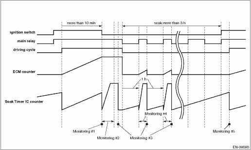
4. GENERAL DRIVING CYCLE
Perform the diagnosis only once when the ignition switch is OFF and when the ignition switch is ON after the soaking of one hour or more.
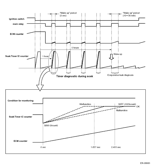
5. DIAGNOSTIC METHOD
Start the count up operation of counters in ECM and in soaking timer IC when the engine is started.
Judge as timer malfunction if the difference between the counter in ECM and counter in soaking timer IC exceeds the allowable limit when the ignition switch is OFF.
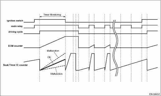
Judge as NG when the following conditions are established.
Malfunction Criteria | Threshold Value |
| (ECM counter) − (Soak timer IC counter) | / ECM counter | > 0.24 |
Reset the counter in soaking timer IC and start the count up operation.
Judge as full count diagnosis malfunction if counter in soaking timer IC is not $3FF (1023 count) after 4 seconds.
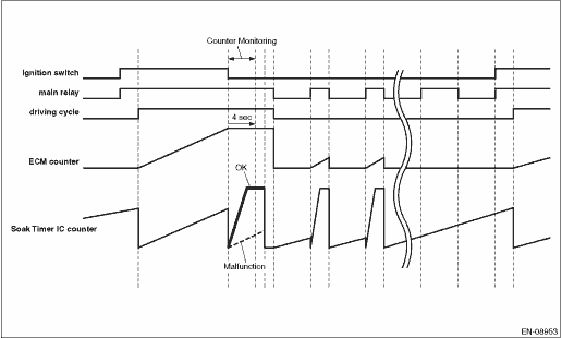
Judge as NG when the following conditions are established.
Malfunction Criteria | Threshold Value |
Soak timer IC counter | ≠ $3FF (1023 count) |
When setting the activation setting time to soaking timer IC, compare the writing value to soaking timer IC with read out value. Judge as malfunction if the values do not match 3 times in a row.
Judge as NG when the following conditions are established.
Malfunction Criteria | Threshold Value |
Value commanded by the ECM | ≠ Value received by the soak timer IC |
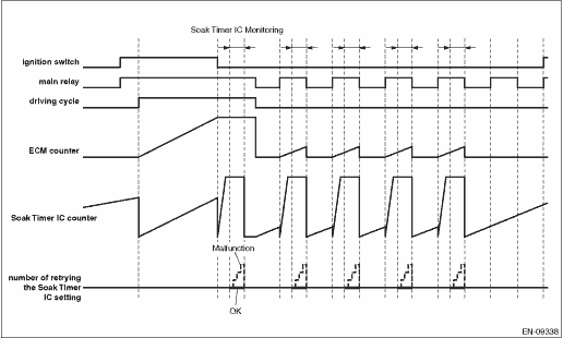
Wake-up at the predetermined interval until 5 or 7 or 9.5 hours have passed after the ignition switch is OFF, and compare the counter in soaking timer IC with the counter in ECM.
Judge as malfunction if the counter in soaking timer IC is counted up to maximum value (1023 counts) when the counter in ECM is 1637 ms, or if the counter in soaking timer IC is not counted up to maximum value (1023 counts) when the counter in ECM is 2455 ms.
Judge as NG when the following conditions are established.
Malfunction Criteria | Threshold Value |
Soak timer IC counter when ECM counter ≤ 1.636 sec | = 1023 count |
Soak timer IC counter when ECM counter ≥ 2.456 sec | ≠ 1023 count |
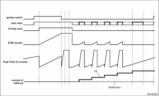
Store the number of wake-up activation when the ECM wakes up by the soaking timer IC.
Next time when the ignition switch is ON, if the number of wake-up activation does not reach the predetermined value even though the counter in soaking timer IC operates 1 hour or more, judge as wake-up malfunction.
Judge as NG when the following conditions are established.
Malfunction Criteria | Threshold Value |
Number of wake-up function commanded from ECM to Soak-timer IC | ≠ Number of actual wake-up ECM |
Time Needed for Diagnosis: Approx. 5 — 9.5 hours
Malfunction Indicator Light Illumination: Illuminates when malfunction occurs in 2 continuous driving cycles.
 Dtc p2530 ignition switch run position circuit
ENGINE (DIAGNOSTICS)(H4DO) > Diagnostic Procedure with Diagnostic Trouble Code (DTC)DTC P2530 IGNITION SWITCH RUN POSITION CIRCUITDTC detecting condition:Immediately at fault recognitionTrouble sym ...
 Dtc u0155 lost communication with instrument panel cluster (ipc) control module
ENGINE (DIAGNOSTICS)(H4DO) > Diagnostic Procedure with Diagnostic Trouble Code (DTC)DTC U0155 LOST COMMUNICATION WITH INSTRUMENT PANEL CLUSTER (IPC) CONTROL MODULENOTE:For the diagnostic procedure, ...
Other materials:
Inspection
EMISSION CONTROL (AUX. EMISSION CONTROL DEVICES)(H4DO) > EGR Control ValveINSPECTION1. Check that the EGR control valve has no deformation, cracks or other damages.2. Measure the resistance between EGR control valve terminals.Terminal No.Standard2 and 122±2 ?2 and 322±2 ?5 and 422±2 ?5 and 622 ...
Removal
HVAC SYSTEM (HEATER, VENTILATOR AND A/C) > Power Transistor (Auto A/C Model)REMOVAL1. Disconnect the ground cable from battery. NOTE">2. Remove the glove box. Glove Box > REMOVAL">3. Remove the screws and remove the duct - foot RH.NOTE:Remove the connector and harness clip of ...
Removal
EXHAUST(H4DO) > Center Exhaust PipeREMOVALCAUTION:Vehicle components are extremely hot after driving. Be wary of receiving burns from heated parts.1. Turn the ignition switch to OFF.2. Lift up the vehicle.3. Remove the bolts, springs, and nuts securing the rear exhaust pipe to the center exhaust ...
