Subaru Crosstrek Service Manual: Dtc p2420 evap system switching valve control circuit high
ENGINE (DIAGNOSTICS)(H4DO) > Diagnostic Procedure with Diagnostic Trouble Code (DTC)
DTC P2420 EVAP SYSTEM SWITCHING VALVE CONTROL CIRCUIT HIGH
DTC detecting condition:
Immediately at fault recognition
CAUTION:
After servicing or replacing faulty parts, perform Clear Memory Mode Clear Memory Mode > OPERATION"> , and Inspection Mode Inspection Mode > PROCEDURE">.
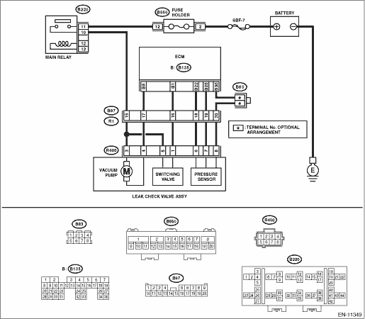
Wiring diagram:
Engine electrical system Engine Electrical System">
| STEP | CHECK | YES | NO |
1.CHECK HARNESS BETWEEN ECM AND LEAK CHECK VALVE ASSEMBLY CONNECTOR.
1) Turn the ignition switch to OFF.
2) Disconnect the connector from the leak check valve assembly.
3) Turn the ignition switch to ON.
4) Measure the voltage between leak check valve assembly and chassis ground.
Connector & terminal
(R400) No. 1 (+) — Chassis ground (−):
Is the voltage 10 V or more?
Repair the short circuit to power in harness between ECM connector and leak check valve assembly connector.
Diagnostic Procedure with Diagnostic Trouble Code (DTC) > DTC P2420 EVAP SYSTEM SWITCHING VALVE CONTROL CIRCUIT HIGH">Go to Step 2.
2.CHECK LEAK CHECK VALVE ASSEMBLY.
1) Turn the ignition switch to OFF.
2) Check the switching valve of the leak check valve assembly. Leak Check Valve Assembly > INSPECTION">
Is the check result OK?
Repair the poor contact in the leak check valve assembly connector.
Replace the leak check valve assembly. Leak Check Valve Assembly">
1. OUTLINE OF DIAGNOSIS
Detect the open or short circuit in Evaporative Leak Check Module switching valve.
Judge as NG if out of specification.
2. COMPONENT DESCRIPTION
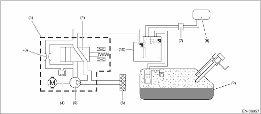
(1) | Leak check valve ASSY | (5) | Vacuum pump | (9) | Fuel tank |
(2) | Switching valve | (6) | Drain filter | (10) | Canister |
(3) | Reference orifice (0.02 inch orifice) | (7) | Purge control solenoid valve | ||
(4) | Pressure sensor | (8) | Intake manifold |
3. EXECUTION CONDITION
Secondary Parameters | Execution condition |
Battery voltage | ≥ 10.9 V |
Evaporative emission system switching valve command | ON |
4. GENERAL DRIVING CYCLE
Always perform the diagnosis continuously.
5. DIAGNOSTIC METHOD
If the duration of time while the following conditions are met is longer than the time indicated, judge as NG.
Malfunction Criteria | Threshold Value |
Measured EVAP system switching valve current | ≥ 12 A |
Time Needed for Diagnosis: 2500 ms
Malfunction Indicator Light Illumination: Illuminates as soon as a malfunction occurs.
 Dtc p2419 evap system switching valve control circuit low
ENGINE (DIAGNOSTICS)(H4DO) > Diagnostic Procedure with Diagnostic Trouble Code (DTC)DTC P2419 EVAP SYSTEM SWITCHING VALVE CONTROL CIRCUIT LOWDTC detecting condition:Immediately at fault recognition ...
 Dtc p2530 ignition switch run position circuit
ENGINE (DIAGNOSTICS)(H4DO) > Diagnostic Procedure with Diagnostic Trouble Code (DTC)DTC P2530 IGNITION SWITCH RUN POSITION CIRCUITDTC detecting condition:Immediately at fault recognitionTrouble sym ...
Other materials:
Air cleaner element
WARNING
Do not operate the engine with the
air cleaner element removed. The air
cleaner element not only filters
intake air but also stops flames if
the engine backfires. If the air
cleaner element is not installed
when the engine backfires, you
could be burned.
CAUTION
When replacing the ...
Installation
REAR SUSPENSION > Rear Trailing LinkINSTALLATIONCAUTION:• Be sure to use a new self-locking nut.• Always tighten the bushing in the state where the vehicle is at curb weight and the wheels are in full contact with the ground.1. Install each part in the reverse order of removal.Tighten ...
Dtc p0123 throttle/pedal position sensor/switch "a" circuit high
ENGINE (DIAGNOSTICS)(H4DO) > Diagnostic Procedure with Diagnostic Trouble Code (DTC)DTC P0123 THROTTLE/PEDAL POSITION SENSOR/SWITCH "A" CIRCUIT HIGHDTC detecting condition:Immediately at fault recognitionTrouble symptom:• Improper idling• Engine stall• Poor driving per ...
