Subaru Crosstrek Service Manual: Dtc p2419 evap system switching valve control circuit low
ENGINE (DIAGNOSTICS)(H4DO) > Diagnostic Procedure with Diagnostic Trouble Code (DTC)
DTC P2419 EVAP SYSTEM SWITCHING VALVE CONTROL CIRCUIT LOW
DTC detecting condition:
Immediately at fault recognition
CAUTION:
After servicing or replacing faulty parts, perform Clear Memory Mode Clear Memory Mode > OPERATION"> , and Inspection Mode Inspection Mode > PROCEDURE">.
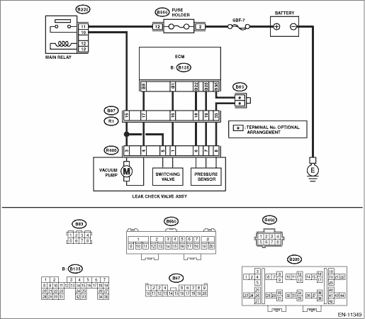
Wiring diagram:
Engine electrical system Engine Electrical System">
| STEP | CHECK | YES | NO |
1.CHECK HARNESS BETWEEN ECM AND LEAK CHECK VALVE ASSEMBLY CONNECTOR.
1) Turn the ignition switch to ON.
2) Measure the voltage between ECM connector and chassis ground.
Connector & terminal
(B135) No. 4 (+) — Chassis ground (−):
Is the voltage 10 V or more?
Diagnostic Procedure with Diagnostic Trouble Code (DTC) > DTC P2419 EVAP SYSTEM SWITCHING VALVE CONTROL CIRCUIT LOW">Go to Step 2.
Diagnostic Procedure with Diagnostic Trouble Code (DTC) > DTC P2419 EVAP SYSTEM SWITCHING VALVE CONTROL CIRCUIT LOW">Go to Step 3.
2.CHECK FOR POOR CONTACT.
Check for poor contact of ECM connector.
Is there poor contact of ECM connector?
Repair the poor contact of ECM connector.
Even if DTC is detected, the circuit has returned to a normal condition at this time. Reproduce the failure, and then perform the diagnosis again.
NOTE:
In this case, temporary open or short circuit of harness or temporary poor contact of connector may be the cause.
3.CHECK POWER SUPPLY TO LEAK CHECK VALVE ASSEMBLY.
Measure the voltage between the leak check valve assembly connector and engine ground.
Connector & terminal
(R400) No. 5 (+) — Engine ground (−):
Is the voltage 10 V or more?
Diagnostic Procedure with Diagnostic Trouble Code (DTC) > DTC P2419 EVAP SYSTEM SWITCHING VALVE CONTROL CIRCUIT LOW">Go to Step 4.
Repair the power supply circuit.
4.CHECK HARNESS BETWEEN ECM AND LEAK CHECK VALVE ASSEMBLY CONNECTOR.
1) Turn the ignition switch to OFF.
2) Disconnect the connector from ECM.
3) Disconnect the connector from the leak check valve assembly.
4) Measure the resistance between leak check valve assembly and chassis ground.
Connector & terminal
(R400) No. 1 — Chassis ground:
Is the resistance 1 M? or more?
Diagnostic Procedure with Diagnostic Trouble Code (DTC) > DTC P2419 EVAP SYSTEM SWITCHING VALVE CONTROL CIRCUIT LOW">Go to Step 5.
Repair the short circuit to ground in harness between ECM connector and leak check valve assembly connector.
5.CHECK HARNESS BETWEEN ECM AND LEAK CHECK VALVE ASSEMBLY CONNECTOR.
Measure the resistance of harness between ECM connector and the leak check valve assembly connector.
Connector & terminal
(B135) No. 1 — (R400) No. 1:
Is the resistance less than 1 ??
Diagnostic Procedure with Diagnostic Trouble Code (DTC) > DTC P2419 EVAP SYSTEM SWITCHING VALVE CONTROL CIRCUIT LOW">Go to Step 6.
Repair the harness and connector.
NOTE:
In this case, repair the following item:
• Open circuit in harness between ECM connector and the leak check valve assembly connector
• Poor contact of coupling connector
6.CHECK LEAK CHECK VALVE ASSEMBLY.
Check the switching valve of the leak check valve assembly. Leak Check Valve Assembly > INSPECTION">
Is the check result OK?
Repair the poor contact in the leak check valve assembly connector.
Replace the leak check valve assembly. Leak Check Valve Assembly">
1. OUTLINE OF DIAGNOSIS
Detect the open or short circuit in Evaporative Leak Check Module switching valve.
Judge as NG if out of specification.
2. COMPONENT DESCRIPTION
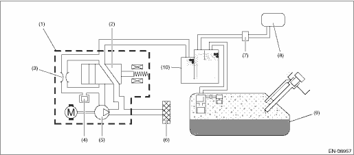
(1) | Leak check valve ASSY | (5) | Vacuum pump | (9) | Fuel tank |
(2) | Switching valve | (6) | Drain filter | (10) | Canister |
(3) | Reference orifice (0.02 inch orifice) | (7) | Purge control solenoid valve | ||
(4) | Pressure sensor | (8) | Intake manifold |
3. EXECUTION CONDITION
Secondary Parameters | Execution condition |
Battery voltage | ≥ 10.9 V |
Evaporative emission system switching valve command | Low |
4. GENERAL DRIVING CYCLE
Always perform the diagnosis continuously.
5. DIAGNOSTIC METHOD
If the duration of time while the following conditions are met is longer than the time indicated, judge as NG.
Malfunction Criteria | Threshold Value |
Measured EVAP system switching valve voltage | 12 V battery system voltage ? 0.34 V |
Time Needed for Diagnosis: 2500 ms
Malfunction Indicator Light Illumination: Illuminates as soon as a malfunction occurs.
 Dtc p2404 evap system leak detection pump sense circuit range/performance
ENGINE (DIAGNOSTICS)(H4DO) > Diagnostic Procedure with Diagnostic Trouble Code (DTC)DTC P2404 EVAP SYSTEM LEAK DETECTION PUMP SENSE CIRCUIT RANGE/PERFORMANCEDTC detecting condition:Detected when tw ...
 Dtc p2420 evap system switching valve control circuit high
ENGINE (DIAGNOSTICS)(H4DO) > Diagnostic Procedure with Diagnostic Trouble Code (DTC)DTC P2420 EVAP SYSTEM SWITCHING VALVE CONTROL CIRCUIT HIGHDTC detecting condition:Immediately at fault recognitio ...
Other materials:
Selection screen
When the
button is pushed and held, the setting screen for each menu can be displayed.
Select the preferred menu by operating
the "
" or "
" switch.
Top menu
Menu option
Description
Time/Date
Time/Date
Set and adjust the time and date. 12h or 24h f ...
Removal
EyeSight > Stereo CameraREMOVALCAUTION:• When the stereo camera or windshield glass has been replaced, removed or installed, always perform the adjustment and inspection of the camera. (When the stereo camera has been replaced with a new part, the camera remains in a failed state until adju ...
Diagnostics with phenomenon Inspection
KEYLESS ACCESS WITH PUSH BUTTON START SYSTEM (DIAGNOSTICS) > Diagnostics with PhenomenonINSPECTION1. KEYLESS ACCESS LOCK/UNLOCK CANNOT BE PERFORMED FROM ANY OF THE DOORSCAUTION:• Check that there are no other registered access keys inside the vehicle.• Inspect LAN system according to ...
