Subaru Crosstrek Service Manual: Dtc p2404 evap system leak detection pump sense circuit range/performance
ENGINE (DIAGNOSTICS)(H4DO) > Diagnostic Procedure with Diagnostic Trouble Code (DTC)
DTC P2404 EVAP SYSTEM LEAK DETECTION PUMP SENSE CIRCUIT RANGE/PERFORMANCE
DTC detecting condition:
Detected when two consecutive driving cycles with fault occur.
CAUTION:
After servicing or replacing faulty parts, perform Clear Memory Mode Clear Memory Mode > OPERATION"> , and Inspection Mode Inspection Mode > PROCEDURE">.
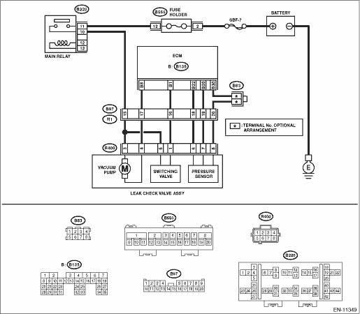
Wiring diagram:
Engine electrical system Engine Electrical System">
| STEP | CHECK | YES | NO |
1.CHECK FOR ANY OTHER DTC ON DISPLAY.
Is any other DTC displayed?
Check the appropriate DTC using the “List of Diagnostic Trouble Code (DTC)”. List of Diagnostic Trouble Code (DTC)">
Diagnostic Procedure with Diagnostic Trouble Code (DTC) > DTC P2404 EVAP SYSTEM LEAK DETECTION PUMP SENSE CIRCUIT RANGE/PERFORMANCE">Go to Step 2.
2.CHECK LEAK CHECK VALVE ASSEMBLY PUMP.
Using the Subaru Select Monitor, operate the leak check valve assembly pump.
NOTE:
For detailed operation procedures, refer to the “Active Test”. Active Test">
Does the leak check valve assembly pump operate?
Diagnostic Procedure with Diagnostic Trouble Code (DTC) > DTC P2404 EVAP SYSTEM LEAK DETECTION PUMP SENSE CIRCUIT RANGE/PERFORMANCE">Go to Step 6.
Diagnostic Procedure with Diagnostic Trouble Code (DTC) > DTC P2404 EVAP SYSTEM LEAK DETECTION PUMP SENSE CIRCUIT RANGE/PERFORMANCE">Go to Step 3.
3.CHECK POWER SUPPLY OF LEAK CHECK VALVE ASSEMBLY.
1) Turn the ignition switch to OFF.
2) Disconnect the connector from the leak check valve assembly.
3) Turn the ignition switch to ON.
4) Measure the voltage between the leak check valve assembly connector and chassis ground.
Connector & terminal
(R400) No. 3 (+) — Chassis ground (−):
Is the voltage 10 V or more?
Diagnostic Procedure with Diagnostic Trouble Code (DTC) > DTC P2404 EVAP SYSTEM LEAK DETECTION PUMP SENSE CIRCUIT RANGE/PERFORMANCE">Go to Step 4.
Repair the harness and connector.
NOTE:
In this case, repair the following item:
• Open circuit in harness between the main relay and the leak check valve assembly connector
• Poor contact of main relay connector
• Poor contact of coupling connector
4.CHECK HARNESS BETWEEN ECM AND LEAK CHECK VALVE ASSEMBLY CONNECTOR.
1) Turn the ignition switch to OFF.
2) Disconnect the connector from ECM.
3) Measure the resistance of harness between ECM connector and the leak check valve assembly connector.
Connector & terminal
(B135) No. 18 — (R400) No. 4:
Is the resistance less than 1 ??
Diagnostic Procedure with Diagnostic Trouble Code (DTC) > DTC P2404 EVAP SYSTEM LEAK DETECTION PUMP SENSE CIRCUIT RANGE/PERFORMANCE">Go to Step 5.
Repair the harness and connector.
NOTE:
In this case, repair the following item:
• Open circuit in harness between ECM connector and the leak check valve assembly connector
• Poor contact of coupling connector
5.CHECK HARNESS BETWEEN ECM AND LEAK CHECK VALVE ASSEMBLY CONNECTOR.
1) Measure the resistance of harness between ECM connector and chassis ground.
Connector & terminal
(B135) No. 18 — Chassis ground:
Is the resistance 1 M? or more?
Replace the leak check valve assembly. Leak Check Valve Assembly">
Repair the short circuit to ground in harness between ECM connector and leak check valve assembly connector.
6.CHECK LEAK CHECK VALVE ASSEMBLY SWITCHING VALVE.
Using the Subaru Select Monitor, operate the leak check valve assembly switching valve.
NOTE:
For detailed operation procedures, refer to the “Active Test”. Active Test">
Does the leak check valve assembly switching valve operate?
Diagnostic Procedure with Diagnostic Trouble Code (DTC) > DTC P2404 EVAP SYSTEM LEAK DETECTION PUMP SENSE CIRCUIT RANGE/PERFORMANCE">Go to Step 10.
Diagnostic Procedure with Diagnostic Trouble Code (DTC) > DTC P2404 EVAP SYSTEM LEAK DETECTION PUMP SENSE CIRCUIT RANGE/PERFORMANCE">Go to Step 7.
7.CHECK POWER SUPPLY OF LEAK CHECK VALVE ASSEMBLY.
1) Turn the ignition switch to OFF.
2) Disconnect the connector from the leak check valve assembly.
3) Turn the ignition switch to ON.
4) Measure the voltage between the leak check valve assembly connector and chassis ground.
Connector & terminal
(R400) No. 5 (+) — Chassis ground (−):
Is the voltage 10 V or more?
Diagnostic Procedure with Diagnostic Trouble Code (DTC) > DTC P2404 EVAP SYSTEM LEAK DETECTION PUMP SENSE CIRCUIT RANGE/PERFORMANCE">Go to Step 8.
Repair the harness and connector.
NOTE:
In this case, repair the following item:
• Open circuit in harness between the main relay and the leak check valve assembly connector
• Poor contact of main relay connector
• Poor contact of coupling connector
8.CHECK HARNESS BETWEEN ECM AND LEAK CHECK VALVE ASSEMBLY CONNECTOR.
1) Turn the ignition switch to OFF.
2) Disconnect the connector from ECM.
3) Measure the resistance of harness between ECM connector and the leak check valve assembly connector.
Connector & terminal
(B135) No. 1 — (R400) No. 1:
Is the resistance less than 1 ??
Diagnostic Procedure with Diagnostic Trouble Code (DTC) > DTC P2404 EVAP SYSTEM LEAK DETECTION PUMP SENSE CIRCUIT RANGE/PERFORMANCE">Go to Step 9.
Repair the harness and connector.
NOTE:
In this case, repair the following item:
• Open circuit in harness between ECM connector and the leak check valve assembly connector
• Poor contact of coupling connector
9.CHECK HARNESS BETWEEN ECM AND LEAK CHECK VALVE ASSEMBLY CONNECTOR.
1) Measure the resistance of harness between ECM connector and chassis ground.
Connector & terminal
(B135) No. 1 — Chassis ground:
Is the resistance 1 M? or more?
Replace the leak check valve assembly. Leak Check Valve Assembly">
Repair the short circuit to ground in harness between ECM connector and leak check valve assembly connector.
10.CHECK EVAPORATIVE EMISSION CONTROL SYSTEM.
Perform drive cycle I. Drive Cycle > PROCEDURE">
Is DTC P2404 displayed on the display?
Replace the leak check valve assembly. Leak Check Valve Assembly">
Even if DTC is detected, the circuit has returned to a normal condition at this time. Reproduce the failure, and then perform the diagnosis again.
NOTE:
In this case, temporary poor contact of connector, temporary open or short circuit of harness may be the cause.
1. OUTLINE OF DIAGNOSIS
NOTE:
For the detection standard, refer to DTC P0455. Diagnostic Procedure with Diagnostic Trouble Code (DTC) > DTC P0455 EVAP SYSTEM (CPC) LEAK DETECTED (LARGE LEAK)">
 Dtc p2402 evap system leak detection pump control circuit high
ENGINE (DIAGNOSTICS)(H4DO) > Diagnostic Procedure with Diagnostic Trouble Code (DTC)DTC P2402 EVAP SYSTEM LEAK DETECTION PUMP CONTROL CIRCUIT HIGHDTC detecting condition:Immediately at fault recogn ...
 Dtc p2419 evap system switching valve control circuit low
ENGINE (DIAGNOSTICS)(H4DO) > Diagnostic Procedure with Diagnostic Trouble Code (DTC)DTC P2419 EVAP SYSTEM SWITCHING VALVE CONTROL CIRCUIT LOWDTC detecting condition:Immediately at fault recognition ...
Other materials:
Inspection
CONTINUOUSLY VARIABLE TRANSMISSION (DIAGNOSTICS) > General DescriptionINSPECTION1. BATTERYCheck the battery. Battery > INSPECTION">2. TRANSMISSION GROUNDMake sure that the ground terminal bolt is tightened securely.Tightening torque:14 N·m (1.4 kgf-m, 10.3 ft-lb)3. OPERATION OF ...
Dtc p2271 o2 sensor signal biased/stuck rich bank 1 sensor 2
ENGINE (DIAGNOSTICS)(H4DO) > Diagnostic Procedure with Diagnostic Trouble Code (DTC)DTC P2271 O2 SENSOR SIGNAL BIASED/STUCK RICH BANK 1 SENSOR 2DTC detecting condition:Detected when two consecutive driving cycles with fault occur.CAUTION:After servicing or replacing faulty parts, perform Clear Me ...
Installation
MECHANICAL(H4DO) > Rocker CoverINSTALLATION1. ROCKER COVER RH1. Install the #1 spark plug pipe gasket and #3 spark plug pipe gasket to the #1 spark plug pipe and #3 spark plug pipe.NOTE:• Use a new #1 spark plug pipe gasket and #3 spark plug pipe gasket.• Apply a light coat of engine ...
