Subaru Crosstrek Service Manual: Dtc p2271 o2 sensor signal biased/stuck rich bank 1 sensor 2
ENGINE (DIAGNOSTICS)(H4DO) > Diagnostic Procedure with Diagnostic Trouble Code (DTC)
DTC P2271 O2 SENSOR SIGNAL BIASED/STUCK RICH BANK 1 SENSOR 2
DTC detecting condition:
Detected when two consecutive driving cycles with fault occur.
CAUTION:
After servicing or replacing faulty parts, perform Clear Memory Mode Clear Memory Mode > OPERATION"> , and Inspection Mode Inspection Mode > PROCEDURE">.
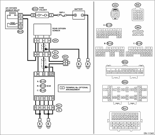
Wiring diagram:
Engine electrical system Engine Electrical System">
| STEP | CHECK | YES | NO |
1.CHECK REAR OXYGEN SENSOR CONNECTOR.
Has water entered the connector?
Completely remove any water inside.
Diagnostic Procedure with Diagnostic Trouble Code (DTC) > DTC P2271 O2 SENSOR SIGNAL BIASED/STUCK RICH BANK 1 SENSOR 2">Go to Step 2.
2.CHECK HARNESS BETWEEN ECM AND REAR OXYGEN SENSOR CONNECTOR.
1) Turn the ignition switch to OFF.
2) Disconnect the connector from ECM.
3) Disconnect the connector from rear oxygen sensor.
4) Measure the resistance of harness between ECM connector and rear oxygen sensor connector.
Connector & terminal
(E135) No. 30 — (E25) No. 4:
(E136) No. 21 — (E25) No. 3:
Is the resistance less than 1 ??
Diagnostic Procedure with Diagnostic Trouble Code (DTC) > DTC P2271 O2 SENSOR SIGNAL BIASED/STUCK RICH BANK 1 SENSOR 2">Go to Step 3.
Repair the open circuit of harness between ECM connector and rear oxygen sensor connector.
3.CHECK HARNESS BETWEEN ECM AND REAR OXYGEN SENSOR CONNECTOR.
Measure the resistance between the ECM connector and engine ground.
Connector & terminal
(E135) No. 30 — Engine ground:
Is the resistance 1 M? or more?
Diagnostic Procedure with Diagnostic Trouble Code (DTC) > DTC P2271 O2 SENSOR SIGNAL BIASED/STUCK RICH BANK 1 SENSOR 2">Go to Step 4.
Repair the short circuit to ground in harness between ECM connector and rear oxygen sensor connector.
4.CHECK EXHAUST SYSTEM.
Check exhaust system parts.
NOTE:
Check the following items.
• Looseness and improper fitting of exhaust system parts
• Damage (crack, hole etc.) of parts
• Damage (crack, hole etc.) between front oxygen (A/F) sensor and rear oxygen sensor
Is there any fault in exhaust system?
Repair or replace faulty parts.
Replace the rear oxygen sensor. Rear Oxygen Sensor">
1. OUTLINE OF DIAGNOSIS
Detect the stuck of rear oxygen sensor voltage in rich state.
Detect the stuck in rich state and judge as NG if rear oxygen sensor voltage remains above the threshold value for predetermined time.
2. COMPONENT DESCRIPTION
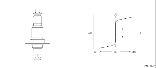
(A) | Electromotive force | (B) | Air fuel ratio | (C) | Lean |
(D) | Rich | (E) | Theoretical air fuel ratio | (F) | Comparative voltage |
3. EXECUTION CONDITION
Secondary parameters | Execution condition |
Battery voltage | ≥ 10.9 V |
Time of fuel cut | ≥ 5000 ms |
Estimated temperature of the rear oxygen sensor element | ≥ 500 °C (932 °F) (CVT model) ≥ 500 °C (932 °F) (MT model) |
4. GENERAL DRIVING CYCLE
Perform the diagnosis only once after the enable conditions have been established.
5. DIAGNOSTIC METHOD
If the duration of time while the following conditions are met is longer than the time indicated, judge as NG.
Malfunction Criteria | Threshold Value |
Output voltage of rear oxygen sensor | > 0.15 V |
Time Needed for Diagnosis: 500 ms
Malfunction Indicator Light Illumination: Illuminates when malfunction occurs in 2 continuous driving cycles.
 Dtc p2270 o2 sensor signal biased/stuck lean bank 1 sensor 2
ENGINE (DIAGNOSTICS)(H4DO) > Diagnostic Procedure with Diagnostic Trouble Code (DTC)DTC P2270 O2 SENSOR SIGNAL BIASED/STUCK LEAN BANK 1 SENSOR 2DTC detecting condition:Detected when two consecutive ...
 Dtc p2401 evap system leak detection pump control circuit low
ENGINE (DIAGNOSTICS)(H4DO) > Diagnostic Procedure with Diagnostic Trouble Code (DTC)DTC P2401 EVAP SYSTEM LEAK DETECTION PUMP CONTROL CIRCUIT LOWDTC detecting condition:Immediately at fault recogni ...
Other materials:
Inspection
SPEED CONTROL SYSTEMS(H4DO) > Accelerator PedalINSPECTION1. CHECK ACCELERATOR PEDAL SENSOR AREA (METHOD WITH CIRCUIT TESTER)1. Remove the glove box. Glove Box > REMOVAL">2. Turn the ignition switch to ON. (Engine OFF)3. Measure the voltage between ECM connector terminals.• Main ...
Installation
CONTINUOUSLY VARIABLE TRANSMISSION(TR580) > Reverse Brake AssemblyINSTALLATION1. Select a washer. Forward Clutch Assembly > ADJUSTMENT">2. Install the selected washer to the reverse brake housing.3. Install the thrust bearing to the reverse brake housing.NOTE:Face the temper color sur ...
Removal
FUEL INJECTION (FUEL SYSTEMS)(H4DO) > Fuel PumpREMOVALWARNING:Place “NO OPEN FLAMES” signs near the working area.CAUTION:• Be careful not to spill fuel.• Catch the fuel from the tubes using a container or cloth.• If the fuel gauge indicates that two thirds or more of ...
