Subaru Crosstrek Service Manual: Dtc p2270 o2 sensor signal biased/stuck lean bank 1 sensor 2
ENGINE (DIAGNOSTICS)(H4DO) > Diagnostic Procedure with Diagnostic Trouble Code (DTC)
DTC P2270 O2 SENSOR SIGNAL BIASED/STUCK LEAN BANK 1 SENSOR 2
DTC detecting condition:
Detected when two consecutive driving cycles with fault occur.
CAUTION:
After servicing or replacing faulty parts, perform Clear Memory Mode Clear Memory Mode > OPERATION"> , and Inspection Mode Inspection Mode > PROCEDURE">.
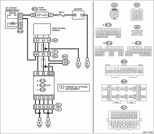
Wiring diagram:
Engine electrical system Engine Electrical System">
| STEP | CHECK | YES | NO |
1.CHECK REAR OXYGEN SENSOR CONNECTOR.
Has water entered the connector?
Completely remove any water inside.
Diagnostic Procedure with Diagnostic Trouble Code (DTC) > DTC P2270 O2 SENSOR SIGNAL BIASED/STUCK LEAN BANK 1 SENSOR 2">Go to Step 2.
2.CHECK HARNESS BETWEEN ECM AND REAR OXYGEN SENSOR CONNECTOR.
1) Turn the ignition switch to OFF.
2) Disconnect the connector from ECM.
3) Disconnect the connector from rear oxygen sensor.
4) Measure the resistance of harness between ECM connector and rear oxygen sensor connector.
Connector & terminal
(E135) No. 30 — (E25) No. 4:
(E136) No. 21 — (E25) No. 3:
Is the resistance less than 1 ??
Diagnostic Procedure with Diagnostic Trouble Code (DTC) > DTC P2270 O2 SENSOR SIGNAL BIASED/STUCK LEAN BANK 1 SENSOR 2">Go to Step 3.
Repair the open circuit of harness between ECM connector and rear oxygen sensor connector.
3.CHECK HARNESS BETWEEN ECM AND REAR OXYGEN SENSOR CONNECTOR.
1) Connect the connector to ECM.
2) Turn the ignition switch to ON.
3) Measure the voltage between rear oxygen sensor connector and engine ground.
Connector & terminal
(E25) No. 3 (+) — Engine ground (−):
Is the voltage 0.15 V or more?
Repair the short circuit to power in the harness between ECM connector and rear oxygen sensor connector.
Diagnostic Procedure with Diagnostic Trouble Code (DTC) > DTC P2270 O2 SENSOR SIGNAL BIASED/STUCK LEAN BANK 1 SENSOR 2">Go to Step 4.
4.CHECK EXHAUST SYSTEM.
Check exhaust system parts.
NOTE:
Check the following items.
• Looseness and improper fitting of exhaust system parts
• Damage (crack, hole etc.) of parts
• Damage (crack, hole etc.) between front oxygen (A/F) sensor and rear oxygen sensor
Is there any fault in exhaust system?
Repair or replace faulty parts.
Replace the rear oxygen sensor. Rear Oxygen Sensor">
1. OUTLINE OF DIAGNOSIS
Detect the stuck of rear oxygen sensor voltage in lean state.
When rear oxygen sensor voltage remains below the threshold value for predetermined time, diagnosis interrupts target air fuel ratio for control and raises output voltage.
Judge as NG detecting the stuck in lean state when rear oxygen sensor voltage remains below the threshold value even after the interrupt control.
2. COMPONENT DESCRIPTION
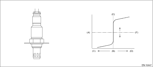
(A) | Electromotive force | (B) | Air fuel ratio | (C) | Lean |
(D) | Rich | (E) | Theoretical air fuel ratio | (F) | Comparative voltage |
3. EXECUTION CONDITION
Secondary parameters | Execution condition |
Battery voltage | ≥ 10.9 V |
Sub feedback | In operation |
Amount of intake air | ≥ 8 g/s (0.28 oz/s) |
Estimated temperature of the rear oxygen sensor element | ≥ 500 °C (932 °F) (CVT model) ≥ 500 °C (932 °F) (MT model) |
Enable conditions at interrupt control are as follows | |
Continuous time when rear oxygen sensor output voltage is less than 0.55 V | ≥ 5 s (CVT model) ≥ 15 s (MT model) |
Air fuel ratio reduced from target air fuel ratio | = Value of Map |
Output voltage of rear oxygen sensor V | 0.000 | 0.150 | 0.200 | 0.400 | 0.600 |
Air fuel ratio reduced from target air fuel ratio % | 15 | 15 | 4 | 4 | 4 |
Output voltage of rear oxygen sensor V | 0.000 | 0.150 | 0.200 | 0.400 | 0.600 |
Air fuel ratio reduced from target air fuel ratio % | 15 | 15 | 4 | 4 | 4 |
4. GENERAL DRIVING CYCLE
Perform the diagnosis only once after the enable conditions have been established.
5. DIAGNOSTIC METHOD
If the duration of time while the following conditions are met is longer than the time indicated, judge as NG.
Malfunction Criteria | Threshold Value |
Output voltage of rear oxygen sensor | < 0.55 V |
Time needed for diagnosis:
• 15 s (CVT model)
• 25 s (MT model)
Malfunction indicator light illumination: Illuminates when malfunction occurs in 2 continuous driving cycles.
 Dtc p2196 a/f /o2 sensor signal biased/stuck rich bank 1 sensor 1
ENGINE (DIAGNOSTICS)(H4DO) > Diagnostic Procedure with Diagnostic Trouble Code (DTC)DTC P2196 A/F /O2 SENSOR SIGNAL BIASED/STUCK RICH BANK 1 SENSOR 1DTC DETECTING CONDITION:Detected when two consec ...
 Dtc p2271 o2 sensor signal biased/stuck rich bank 1 sensor 2
ENGINE (DIAGNOSTICS)(H4DO) > Diagnostic Procedure with Diagnostic Trouble Code (DTC)DTC P2271 O2 SENSOR SIGNAL BIASED/STUCK RICH BANK 1 SENSOR 2DTC detecting condition:Detected when two consecutive ...
Other materials:
Installation
STARTING/CHARGING SYSTEMS(H4DO) > Battery Current & Temperature SensorINSTALLATION1. BATTERY CURRENT SENSORInstall in the reverse order of removal.Tightening torque: General Description > COMPONENT">3 N·m (0.3 kgf-m, 2.2 ft-lb)2. BATTERY TEMPERATURE SENSORInstall in the reve ...
Cleaning aluminum wheels
Promptly wipe the aluminum wheels
clean of any kind of grime or agent. If dirt
is left on too long, it may be difficult to
clean off.
Do not use soap containing grit to
clean the wheels. Be sure to use a neutral
cleaning agent, and later rinse thoroughly
with water. Do not clean the ...
Removal
MECHANICAL(H4DO) > Cam SprocketREMOVAL1. CAM SPROCKET RHNOTE:When replacing a single part, perform the work with the engine assembly installed to body.• Intake cam sprocket RH1. Remove the chain cover. Chain Cover > REMOVAL">2. Remove the timing chain RH. Timing Chain Assembly ...
