Subaru Crosstrek Service Manual: Dtc p2196 a/f /o2 sensor signal biased/stuck rich bank 1 sensor 1
ENGINE (DIAGNOSTICS)(H4DO) > Diagnostic Procedure with Diagnostic Trouble Code (DTC)
DTC P2196 A/F /O2 SENSOR SIGNAL BIASED/STUCK RICH BANK 1 SENSOR 1
DTC DETECTING CONDITION:
Detected when two consecutive driving cycles with fault occur.
CAUTION:
After servicing or replacing faulty parts, perform Clear Memory Mode Clear Memory Mode > OPERATION"> , and Inspection Mode Inspection Mode > PROCEDURE">.
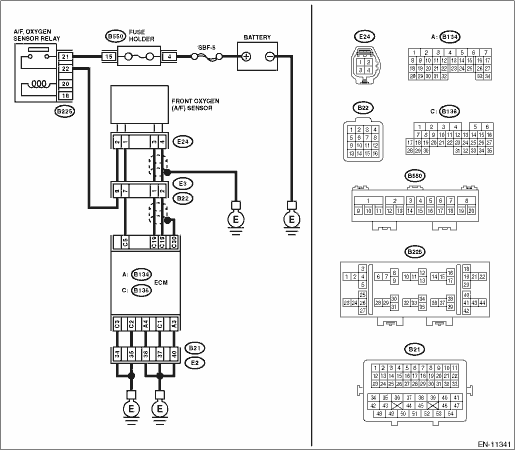
WIRING DIAGRAM:
Engine electrical system Engine Electrical System">
| STEP | CHECK | YES | NO |
1.CHECK FRONT OXYGEN (A/F) SENSOR CONNECTOR AND COUPLING CONNECTOR.
Has water entered the connector?
Completely remove any water inside.
Diagnostic Procedure with Diagnostic Trouble Code (DTC) > DTC P2196 A/F /O2 SENSOR SIGNAL BIASED/STUCK RICH BANK 1 SENSOR 1">Go to Step 2.
2.CHECK HARNESS BETWEEN ECM AND FRONT OXYGEN (A/F) SENSOR CONNECTOR.
1) Turn the ignition switch to OFF.
2) Disconnect the connector from ECM.
3) Measure the resistance between ECM connector and chassis ground.
Connector & terminal
(B136) No. 19 — Chassis ground:
(B136) No. 18 — Chassis ground:
Is the resistance 1 M? or more?
Diagnostic Procedure with Diagnostic Trouble Code (DTC) > DTC P2196 A/F /O2 SENSOR SIGNAL BIASED/STUCK RICH BANK 1 SENSOR 1">Go to Step 3.
Repair the short circuit to ground in harness between ECM connector and front oxygen (A/F) sensor connector.
3.CHECK OUTPUT SIGNAL FOR ECM.
1) Connect the connector to ECM.
2) Turn the ignition switch to ON.
3) Measure the voltage between ECM connector and chassis ground.
Connector & terminal
(B136) No. 19 (+) — Chassis ground (−):
Is the voltage 4.5 V or more?
Diagnostic Procedure with Diagnostic Trouble Code (DTC) > DTC P2196 A/F /O2 SENSOR SIGNAL BIASED/STUCK RICH BANK 1 SENSOR 1">Go to Step 5.
Diagnostic Procedure with Diagnostic Trouble Code (DTC) > DTC P2196 A/F /O2 SENSOR SIGNAL BIASED/STUCK RICH BANK 1 SENSOR 1">Go to Step 4.
4.CHECK OUTPUT SIGNAL FOR ECM.
Measure the voltage between ECM connector and chassis ground.
Connector & terminal
(B136) No. 18 (+) — Chassis ground (−):
Is the voltage 4.95 V or more?
Diagnostic Procedure with Diagnostic Trouble Code (DTC) > DTC P2196 A/F /O2 SENSOR SIGNAL BIASED/STUCK RICH BANK 1 SENSOR 1">Go to Step 5.
Replace the front oxygen (A/F) sensor. Front Oxygen (A/F) Sensor">
5.CHECK OUTPUT SIGNAL FOR ECM.
Measure the voltage between ECM connector and chassis ground.
Connector & terminal
(B136) No. 19 (+) — Chassis ground (−):
(B136) No. 18 (+) — Chassis ground (−):
Is the voltage 8 V or more?
Repair the short circuit to power in the harness between ECM connector and front oxygen (A/F) sensor connector. After repair, replace the ECM. Engine Control Module (ECM)">
Repair the poor contact of ECM connector.
1. OUTLINE OF DIAGNOSIS
Detect that λ value remains high.
Judge as NG when lambda value is abnormal in accordance with λ value of front oxygen (A/F) sensor and running conditions such as vehicle speed, amount of intake air, engine coolant temperature, sub feedback control, etc.
λ value = Actual air fuel ratio/Theoretical air fuel ratio |
λ > 1: Lean |
λ < 1: Rich |
2. COMPONENT DESCRIPTION
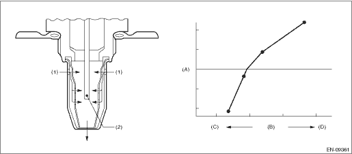
(A) | Electromotive force | (B) | Air fuel ratio | (C) | Rich |
(D) | Lean | ||||
(1) | Exhaust gas | (2) | Zirconia element oxygen |
3. EXECUTION CONDITION
Secondary parameters | Execution condition |
Battery voltage | ≥ 10.9 V |
Barometric pressure | > 75.1 kPa (563 mmHg, 22.2 inHg) |
Main feedback | In operation |
Amount of intake air | ≥ 6 g/s (0.21 oz/s) |
Estimated temperature of the rear oxygen sensor element | ≥ 500 °C (932 °F) |
4. GENERAL DRIVING CYCLE
Perform the diagnosis continuously during driving.
5. DIAGNOSTIC METHOD
If the duration of time while the following conditions are met is longer than the time indicated, judge as NG.
Malfunction Criteria | Threshold Value |
λ value | < 0.85 |
Output voltage value of rear oxygen sensor | < 0.2 V |
Time needed for diagnosis: 10 seconds
Malfunction indicator light illumination: Illuminates when malfunction occurs in 2 continuous driving cycles.
 Dtc p2195 a/f /o2 sensor signal biased/stuck lean bank 1 sensor 1
ENGINE (DIAGNOSTICS)(H4DO) > Diagnostic Procedure with Diagnostic Trouble Code (DTC)DTC P2195 A/F /O2 SENSOR SIGNAL BIASED/STUCK LEAN BANK 1 SENSOR 1DTC detecting condition:Detected when two consec ...
 Dtc p2270 o2 sensor signal biased/stuck lean bank 1 sensor 2
ENGINE (DIAGNOSTICS)(H4DO) > Diagnostic Procedure with Diagnostic Trouble Code (DTC)DTC P2270 O2 SENSOR SIGNAL BIASED/STUCK LEAN BANK 1 SENSOR 2DTC detecting condition:Detected when two consecutive ...
Other materials:
Dtc p0441 evap system (cpc) incorrect purge flow
ENGINE (DIAGNOSTICS)(H4DO) > Diagnostic Procedure with Diagnostic Trouble Code (DTC)DTC P0441 EVAP SYSTEM (CPC) INCORRECT PURGE FLOWDTC DETECTING CONDITION:Detected when two consecutive driving cycles with fault occur.TROUBLE SYMPTOM:Improper idlingCAUTION:After servicing or replacing faulty part ...
Inspection
FUEL INJECTION (FUEL SYSTEMS)(H4DO) > Mass Air Flow and Intake Air Temperature SensorINSPECTION1. CHECK THE MASS AIR FLOW SENSOR UNIT1. Connect the battery positive terminal to terminal No. 3 and the battery ground terminal to terminal No. 4, the circuit tester positive terminal to terminal No. 5 ...
Inspection
SECURITY AND LOCKS > Relay and FuseINSPECTION1. CHECK FUSE1. Remove the fuse and inspect visually.2. If the fuse is blown out, replace the fuse.NOTE:If the fuse is blown again, check the system wiring harness.2. CHECK RELAY1. Check the resistance between relay terminals.Terminal No.Inspection con ...
