Subaru Crosstrek Service Manual: Installation
MECHANICAL(H4DO) > Rocker Cover
INSTALLATION
1. ROCKER COVER RH
1. Install the #1 spark plug pipe gasket and #3 spark plug pipe gasket to the #1 spark plug pipe and #3 spark plug pipe.
NOTE:
• Use a new #1 spark plug pipe gasket and #3 spark plug pipe gasket.
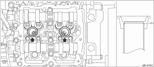
• Apply a light coat of engine oil to the #1 spark plug pipe gasket and #3 spark plug pipe gasket, and insert them onto the spark plug pipe edge (A).
2. Install the rocker cover gasket RH to the rocker cover RH.
NOTE:
Use a new rocker cover gasket RH.
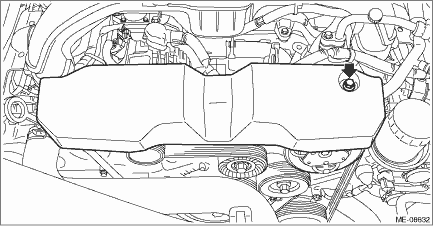
3. Apply liquid gasket to the mating surface of rocker cover RH as shown in the figure.
NOTE:
• Before applying liquid gasket, degrease the old liquid gasket seal surface of the engine.
• Be careful not to allow liquid gasket to be squeezed out from rocker cover RH.
• Install within 5 min. after applying liquid gasket.
Liquid gasket:
THREE BOND 1217G (Part No. K0877Y0100), THREE BOND 1217H or equivalent
Liquid gasket applying diameter:
3.5±0.5 mm (0.1378±0.0197 in)
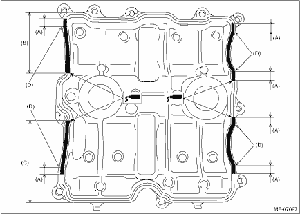
(A) | 10 mm (0.394 in) or more | (C) | 89 mm (3.504 in) or more | (D) | Arch starting point |
(B) | 68 mm (2.677 in) or more |
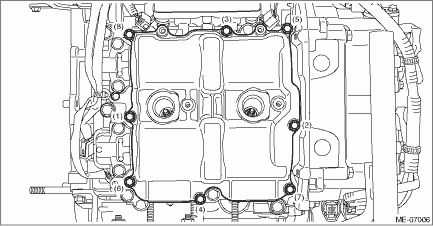
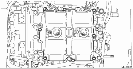
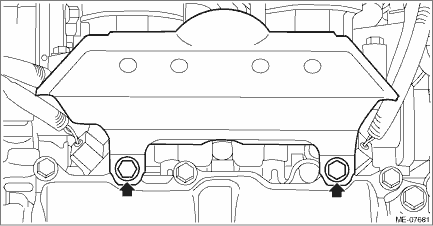
4. Set the rocker cover RH, and tighten the bolts in numerical order as shown in the figure.
Tightening torque:
6.4 N·m (0.7 kgf-m, 4.7 ft-lb)
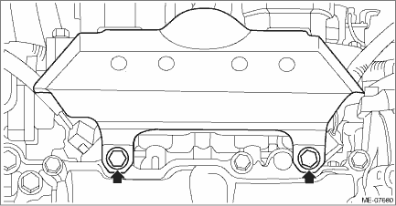
5. Install the intake manifold protector RH.
Tightening torque:
6.4 N·m (0.7 kgf-m, 4.7 ft-lb)
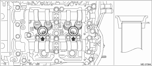
6. Install the #1 ignition coil and the #3 ignition coil. Ignition Coil > INSTALLATION">
7. When working on the vehicle
NOTE:
When working on the vehicle, perform the following steps also.
(1) Install the front exhaust pipe. Front Exhaust Pipe > INSTALLATION">
(2) Install the air intake boot. Air Intake Boot > INSTALLATION">
(3) Install the air cleaner case. Air Cleaner Case > INSTALLATION">
2. ROCKER COVER LH
1. When working on the vehicle
NOTE:
When working on the vehicle, perform the following steps also.
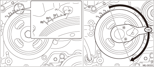
(1) Align the timing mark (B) on crank pulley to the 0° in timing gauge (A) on chain cover as shown in the figure, and turn the crankshaft by 180° clockwise from that position.
NOTE:
This procedure is required to prevent the rocker cover LH and the cam lobe of camshaft LH contacting with each other when installing the rocker cover LH.
2. Install the #2 spark plug pipe gasket and #4 spark plug pipe gasket to the #2 spark plug pipe and #4 spark plug pipe.
NOTE:
• Use a new #2 spark plug pipe gasket and #4 spark plug pipe gasket.
• Apply a light coat of engine oil to the #2 spark plug pipe gasket and #4 spark plug pipe gasket, and insert them onto the spark plug pipe edge (A).
3. Install the rocker cover gasket LH to the rocker cover LH.
NOTE:
Use a new rocker cover gasket LH.
4. Apply liquid gasket to the mating surface of rocker cover LH as shown in the figure.
NOTE:
• Before applying liquid gasket, degrease the old liquid gasket seal surface of the engine.
• Be careful not to allow liquid gasket to be squeezed out from rocker cover LH.
• Install within 5 min. after applying liquid gasket.
Liquid gasket:
THREE BOND 1217G (Part No. K0877Y0100), THREE BOND 1217H or equivalent
Liquid gasket applying diameter:
3.5±0.5 mm (0.1378±0.0197 in)
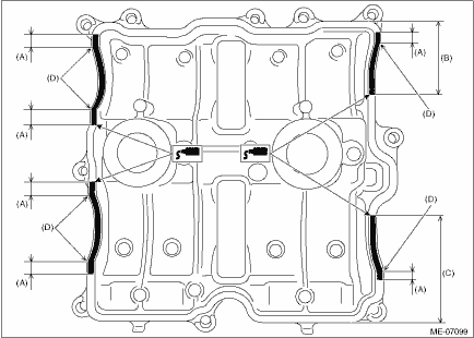
(A) | 10 mm (0.394 in) or more | (C) | 73 mm (2.874 in) or more | (D) | Arch starting point |
(B) | 51 mm (2.008 in) or more |
5. Set the rocker cover LH, and tighten the bolts in numerical order as shown in the figure.
Tightening torque:
6.4 N·m (0.7 kgf-m, 4.7 ft-lb)
6. Install the intake manifold protector LH.
Tightening torque:
6.4 N·m (0.7 kgf-m, 4.7 ft-lb)
7. Install the #2 ignition coil and the #4 ignition coil. Ignition Coil > INSTALLATION">
8. When working on the vehicle
NOTE:
When working on the vehicle, perform the following steps also.
(1) Install the air intake duct. Air Intake Duct > INSTALLATION">
(2) Install the battery. Battery > INSTALLATION">
(3) Install the V-belt cover.
Tightening torque:
7 N·m (0.7 kgf-m, 5.2 ft-lb)
 Removal
MECHANICAL(H4DO) > Rocker CoverREMOVAL1. ROCKER COVER RHNOTE:When replacing a single part, perform the work with the engine assembly installed to body.1. When working on the vehicleNOTE:When workin ...

Other materials:
Remote engine start system (dealer option)
WARNING
Before using the remote engine start feature on the Subaru Ascent, always
review and understand all safety precautions related to engine starting.
Proper use of the system is essential to prevent accidents and ensure
safe operation.
Never activate the Subaru Ascent rem ...
Installation
BRAKE > Front Disc RotorINSTALLATIONNOTE:Before installation, remove mud and foreign matter from the caliper body assembly.1. Before installation, check the front disc rotor. Front Disc Rotor > INSPECTION">2. Install each part in the reverse order of removal.Tightening torque:Brake ho ...
Snow tires
WARNING
When replacing or installing winter
tire(s), all four tires must be
the same for following items.
(a) Size
(b) Circumference
(c) Speed symbol
(d) Load index
(e) Construction
(f) Manufacturer
(g) Brand (tread pattern)
(h) Degrees of wear
For the items (a) to (d), you must
obey th ...
