Subaru Crosstrek Service Manual: Repair
EXTERIOR/INTERIOR TRIM > Front Bumper
REPAIR
1. COATING METHOD FOR PP BUMPER
Process No. | Process name | Job contents | |
1 | Bumper installation | Place the bumper on a paint worktable as required. Use the paint worktable conforming to inner shape of bumper if possible. | Cross section of bumper |
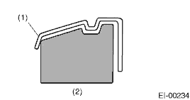
(1) Bumper
(2) Paint worktable
2
Masking
Mask specified part (black base) with masking tape. Use masking tape for PP.
3
Degreasing/cleaning
Clean all parts to be painted with appropriate cleaning solvent, normal alcohol, etc. to remove dirt, oil, grease, etc.
4
Primer paint
Apply primer to all parts to be painted, using spray gun. Use primer (clear).
5
Drying
Dry at normal temperature. [10 — 15 min. at 20°C (68°F)]
In half-dried condition, PP primer paint is dissolved by solvent, e.g. thinner, etc.
Therefore, if dust or dirt must be removed, use ordinary alcohol etc.
6
Top coat paint (I)
Non-colored
Metallic paint
Use section (block) paint for top coat.
For paint/hardener mixture, observe the specifications recommended by the manufacturers.
• Viscosity: 10 — 13 sec./20°C (68°F)
• Film thickness: 35 — 45 µ
• Spraying pressure: 245 — 343 kPa
(2.5 — 3.5 kgf/cm2, 36 — 50 psi)
Use section (block) paint for top coat.
For paint/hardener mixture, observe the specifications recommended by the manufacturers.
• Viscosity: 10 — 13 sec./20°C (68°F)
• Film thickness: 15 — 20 µ
• Spraying pressure: 245 — 343 kPa
(2.5 — 3.5 kgf/cm2, 36 — 50 psi)
7
Drying
Not required.
Dry at normal temperature [at least 10 min. at 20°C (68°F)].
In half-dried condition, avoid dust, dirt.
8
Top coat paint (II)
Not required.
Apply a clear coat to parts with top coat paint (I), three times at 5 — 7 minute intervals.
For paint/hardener mixture, observe the specifications recommended by the manufacturers.
• Viscosity: 14 — 16 sec./20°C (68°F)
• Film thickness: 25 — 30 µ
• Spraying pressure: 245 — 343 kPa
(2.5 — 3.5 kgf/cm2, 36 — 50 psi)
9
Drying
60°C (140°F), 60 min. or 80°C (176°F), 30 min.
If the temperature is higher than 80°C (176°F), PP may be deformed. Keep maximum temperature at 80°C (176°F) or less.
10
Inspection
Check paint.
11
Removal of masking
Remove the masking tape applied in procedure 2.
2. REPAIR INSTRUCTIONS FOR COLORED PP BUMPER
NOTE:
All PP bumpers are provided with a grained surface, and if the surface is damaged, it cannot normally be restored to its former condition. Damages limited to the shallow scratches that cause only a change in the luster of the base material or coating, can be almost fully restored. Before repairing a damaged area, explain this point to the customer and obtain an understanding about the matter.
Repair methods are outlined below, based on a classification of the extent of damage.
1. Minor damage causing only a change in the luster of the bumper due to a light touch
Almost restorable.
Process No. | Process name | Job contents | |
1 | Cleaning | Clean the area to be repaired using water. | |
2 | Sanding | Grind the repairing area with #500 sand paper in a “feathering” motion. | |
3 | Finish | Resin section | Coated section |
Repeatedly apply wax to the affected area using soft cloth (such as flannel). Recommended wax: Tire wax or equivalent | Perform either the same procedures as for the resin section or process No. 18 and subsequent in section 3), depending on the degree and nature of damage. | ||
Polish the waxed area with clean cloth after 5 — 10 minutes. | |||
2. Deep damage caused by scratching with fences etc.
A dent cannot be repaired but a whitened or swelled part can be removed.
Process No. | Process name | Job contents | |
1 | Cleaning | Clean the damaged area with water. | |
2 | Removal of damaged area | Cut off protruding area, if any, due to collision, using a putty knife. | |
3 | Sanding | Grind the affected area with #100 — #500 sand paper. | |
4 | Finish | Resin section | Coated section |
Same as process No. 3 in section “1)”. | Perform process No. 12 and subsequent operations in section “3)”. | ||
3. Deep damage such as a break or hole that requires filling
Much of the peripheral grained surface must be sacrificed for repair. The degree of restoration is not really worth the expense. (The surface, however, will become almost flush with adjacent areas.)
Process No. | Process name | Job contents | |
1 | Bumper removal | Remove the bumper as required. | |
2 | Removal of parts | Remove the parts built into bumper as required. | |
3 | Bumper placement | Place the bumper on a paint worktable as required. It is recommended to use the paint worktable conforming to internal shape of bumper. | Cross section of bumper |
(1) Bumper
(2) Paint worktable
4
Surface preparation
Remove dust, oil, etc. from areas to be repaired and surrounding areas, using an appropriate solvent (appropriate cleaning solvent or alcohol, etc.).
5
Cutting
If the damage is a crack or a hole, cut a guide slit of 20 to 30 mm (0.79 to 1.18 in) in length along the crack or hole up to the bumper base surface. Next, use a knife or grinder to carve a V-shaped groove in the area for repair.
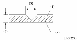
(1) Paint surface
(2) PP base surface
(3) 20 — 30 mm (0.79 — 1.18 in)
(4) 3 mm (0.12 in)
6
Sanding (I)
Grind beveled surface with sand paper (#40 — #60) to smooth finish.
7
Cleaning
Clean the sanded surface with the same solvent as used in process No. 4.
8
Temporary welding
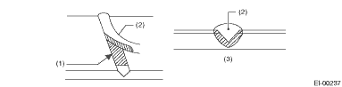
Grind the side just opposite the beveled area with sand paper (#40 — #60) and clean using a solvent.
Temporarily spot-weld the side, using PP welding rod and heater gun.

(1) Welded point (Use heater gun and PP welding rod)
(2) PP base surface
(3) Beveled section
NOTE:
• Do not melt welding rod until it flows out. This results in reduced strength.
• Leave the welded spot unattended until it cools completely.
9
Welding
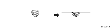
Using a heater gun and PP welding rod, weld the beveled spot while melting both the rod and damaged area.
(1) Welding rod
(2) Melt hatched area
(3) Section
NOTE:
• Melt the sections indicated by hatched area.
• Do not melt the welding rod until it flows out, in order to provide strength.
• Always keep the heater gun 1 to 2 cm (0.4 to 0.8 in) away from the welding spot.
• Leave the welded spot unattended until it cools completely.
10
Sanding (II)
Remove excess part of weld with a putty knife. If a drill or disc wheel is used instead of the knife, operate it at less than 1,500 r/min and grind the excess part little by little. A higher rpm will cause the PP substrate to melt from the heat.
Sand the welded spot smooth with #240 sand paper.
11
Masking
Mask the black substrate section using masking tape.
12
Cleaning/degreasing
Completely clean the entire coated area, using solvent similar to that used in process No. 4.
13
Primer coating
Apply a coat of primer for bumpers to the repaired surface and its surrounding areas. Mask these areas, if necessary.
NOTE:
Be sure to apply a coat of primer using a spray gun at a pressure of 245 — 343 kPa (2.5 — 3.5 kgf/cm2, 36 — 50 psi).
14
Leave unattended
Leave the repaired area unattended at 20°C (68°F) for 10 to 15 minutes until primer is half-dry.
NOTE:
If dirt or dust comes in contact with the coated area, wipe it off with a cloth dampened with alcohol. (Do not use thinner since it could melt the coated area.)
15
Surfacer coating
Apply a coat of surfacer for PP bumpers to the repaired area two or three times at an interval of 3 — 5 minutes.
For surfacer/hardener mixture, viscosity and paint thickness, observe the specifications of the surfacers to be used.
16
Drying
Allow the coated surface to dry for 20 minutes at 20°C (68°F) [or 30 minutes at 60°C (140°F)].
17
Sanding (III)
Sand the coated surface and its surrounding areas using #400 sand paper and water.
18
Cleaning/degreasing
Same as process No. 12.
19
Top coat (I)
Non-colored
Metallic paint
Use a “block” coating method.
For paint/hardener mixture, observe the specifications recommended by the manufacturers.
• Viscosity: 11 — 13 sec./20°C (68°F)
• Coating film thickness: 40 — 50 µ
• Spraying pressure: 245 — 343 kPa
(2.5 — 3.5 kgf/cm2, 36 — 50 psi)
Use a “block” coating method.
For paint/hardener mixture, observe the specifications recommended by the manufacturers.
• Viscosity: 11 — 13 sec./20°C (68°F)
• Coating film thickness: 20 — 30 µ
• Spraying pressure: 245 — 343 kPa
(2.5 — 3.5 kgf/cm2, 36 — 50 psi)
20
Leave unattended
Not required.
Leave unattended at 20°C (68°F) for at least 10 minutes until the topcoated area is half-dry.
NOTE:
Be careful to keep dust or dirt from coming in contact with the affected area.
21
Top coat (II)
Not required.
Apply a clear coat three times at an interval of 3 to 5 minutes.
For paint/hardener mixture, observe the specifications recommended by the manufacturers.
• Viscosity: 10 — 13 sec./20°C (68°F)
• Coating film thickness: 20 — 30 µ
• Spraying pressure: 245 — 343 kPa
(2.5 — 3.5 kgf/cm2, 36 — 50 psi)
22
Drying
Allow the coated surface to dry for two hours at 20°C (68°F) or 30 minutes at 60°C (140°F).
NOTE:
Do not allow the temperature to exceed 80°C (176°F) since this will deform the PP substrate.
23
Inspection
Carefully check the condition of the repaired area.
24
Removal of masking
Remove the masking tape applied in process No. 11 and 13.
25
Parts installation
Install parts on the bumper in reverse order of removal.
26
Bumper installation
Install the bumper.
 Installation
EXTERIOR/INTERIOR TRIM > Front BumperINSTALLATION1. Install each part in the reverse order of removal.2. Secure the flange section of the bumper face - front to the bracket - front bumper side.CAUT ...
 Removal
EXTERIOR/INTERIOR TRIM > Front BumperREMOVAL1. Disconnect the ground cable from battery. NOTE">2. Remove the bumper face - front.(1) Remove the screw and clips, and turn over the mud guard ...
Other materials:
Installation
EXTERIOR/INTERIOR TRIM > Instrument Panel AssemblyINSTALLATIONCAUTION:• Before handling the airbag system components, refer to “CAUTION” of “General Description” in “AIRBAG SYSTEM”. General Description > CAUTION">• After installing the p ...
Clear setting
1. Perform the preparation steps according
to "Preparation for maintenance settings"
2. Operate the " " or "
" switch to
select the "Clear All Settings" item. Then
push the button.
3. The system will prompt a Yes/No
dialogue ("No" is selected first). To clear
all maintenance settin ...
Dtc b2a03 gps antenna circuit
TELEMATICS SYSTEM (DIAGNOSTICS) > Diagnostic Procedure with Diagnostic Trouble Code (DTC)DTC B2A03 GPS ANTENNA CIRCUITDiagnosis start condition:When ignition switch is ON.DTC detecting condition:Any of the followings continues for 5 seconds or more.• GPS antenna impedance is more than 1 M?. ...
