Subaru Crosstrek Service Manual: Removal
AIRBAG SYSTEM > Side Airbag Sensor
REMOVAL
CAUTION:
• Before handling the airbag system components, refer to “CAUTION” of “General Description” in “AIRBAG SYSTEM”. General Description > CAUTION">
• Airbag system satellite safing sensor is located in the lower of the rear seat cushion center. Be careful not to apply strong impact to the sensor when working with the rear seat cushion removed.
1. Move the seat all the way forward, from which the side airbag sensor is to be removed.
NOTE:
This is to remove the seat belt retractor assembly.
2. Turn the ignition switch to OFF.
3. Disconnect the ground cable from battery and wait for at least 60 seconds before starting work. NOTE">
4. Remove the rear seat cushion assembly. Rear Seat > REMOVAL">
5. Remove the following lower inner trims. (On the side where the side airbag sensor is removed) Lower Inner Trim > REMOVAL">
• Cover side sill - front INN
• Cover side sill - rear INN
• Trim panel - center pillar LWR
6. Remove the seat belt retractor. (On the side where the side airbag sensor is removed)
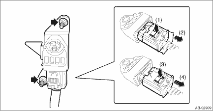
(1) Turn over the floor mat to disconnect the belt tension sensor connector. Airbag Connector > PROCEDURE">
NOTE:
Also disconnect the connector of the passenger’s lap seat belt pretensioner.
(2) Remove the bolt to remove the seat belt retractor.
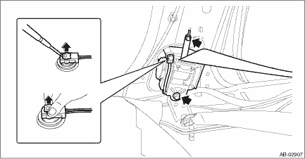
7. Remove the nuts and then remove the side airbag sensor. Airbag Connector > PROCEDURE">
CAUTION:
• Do not separate the side airbag sensor and bracket. It causes the airbag system malfunction.
• If the sensor is removed from the bracket, be sure to replace with a new part.
 Installation
AIRBAG SYSTEM > Side Airbag SensorINSTALLATIONCAUTION:Do not reuse the bolt and nut.Always replace with the specified new bolts and nuts.1. Before installation, inspect the following items and repl ...
 Airbag connector Procedure
AIRBAG SYSTEM > Airbag ConnectorPROCEDURE1. POWER SUPPLY1. How to disconnect:CAUTION:When pulling the slide lock or disconnecting connector, be sure to hold the connector, not the harness.(1) Push ...
Other materials:
Steering warning light does not come on
POWER ASSISTED SYSTEM (POWER STEERING) (DIAGNOSTICS) > STEERING Warning LightSTEERING WARNING LIGHT DOES NOT COME ON1. POWER STEERING ASSIST ENABLEDDetecting condition:• Defective combination meter• Defective harnessTrouble symptom:When the ignition switch is turned to ON (engine OFF) ...
Removal
LIGHTING SYSTEM > Day Time Running ResistorREMOVAL1. Disconnect the ground cable from battery. NOTE">2. Lift up the vehicle.3. Remove the screw and clips, and turn over the front side of the mud guard - front.4. Remove the resistor assembly - daytime running light.CAUTION:The resistor ma ...
Engine control module (ecm) i/o signal Electrical specification
ENGINE (DIAGNOSTICS)(H4DO) > Engine Control Module (ECM) I/O SignalELECTRICAL SPECIFICATION1. ENGINE CONTROL MODULE (ECM)DescriptionConnector No.Terminal No.Signal (V)NoteIgnition SW ON(Engine OFF)Engine ON(Idling)Crankshaft position sensor(+) signalB1361650 or 5Waveform*(−) signalB1362700 ...
