Subaru Crosstrek Service Manual: Removal
EXTERIOR/INTERIOR TRIM > Front Bumper
REMOVAL
1. Disconnect the ground cable from battery. NOTE">
2. Remove the bumper face - front.
(1) Remove the screw and clips, and turn over the mud guard - front.
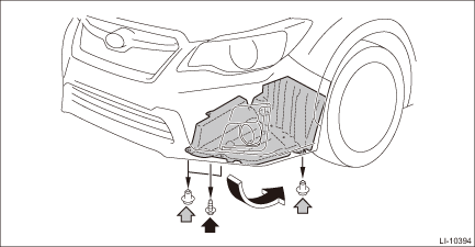
(2) Disconnect the connectors of the left and right fog light assembly - front. (Model with fog light)
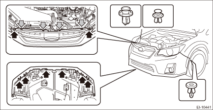
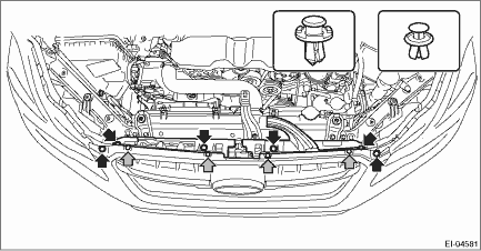
(3) Remove the clips at the upper side of the bumper face - front.
(4) Remove the clips from the fender.
(5) Remove the clips at the lower side of the bumper face - front.
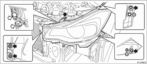
(6) Apply protective tape (A) to the light assembly - head.
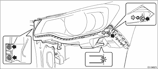
(7) Detach the flange section on the bumper face side from the bracket - front bumper side.
CAUTION:
Do not pull forcibly. It may damage the flange section on the bumper face - front side when it comes off from the claws of the bracket - front bumper.
NOTE:
Remove the bumper face - front according to the following procedures.
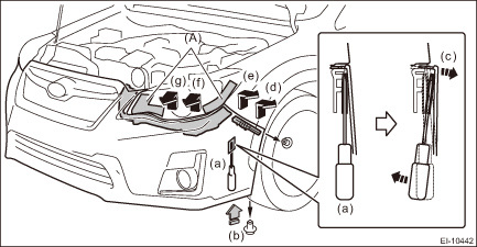
1. Remove the clips, turn over the mud guard, and insert a flat tip screwdriver with protection for damage prevention into the clearance between bumper and bracket. (a)
2. Push out the bumper with the flat tip screwdriver while pushing up the bumper from below. (b), (c)
3. Release the engagement of clips in the order of (d) to (g) while pushing up the bumper from below.
4. Perform the same procedures to remove the opposite side.
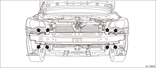
3. Remove the bolts, and remove the bumper beam COMPL - front.
4. Remove the clip, and remove the bracket - grille.
CAUTION:
To prevent damage to the bracket - grille, make sure to remove all clips.
NOTE:
The bracket - grille can be removed without removing the bumper face - front.
5. Remove the bracket - front center LWR.
(1) Remove the bolts and clips, and turn over the under cover - front.
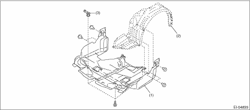
(1) | Under cover - front | (2) | Mud guard - front | (3) | Spacer - under cover |
(2) Remove the bolts, and remove the bracket - front center LWR.
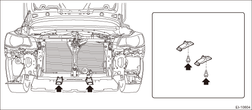
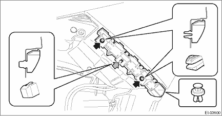
6. Remove the bolts and clips, and remove the bracket - front bumper corner.
NOTE:
When removing the bracket - front bumper corner only, do not remove the light assembly - head.
7. Remove the bracket - front bumper side.
(1) Remove the bolts and clips, and remove the light assembly - head and the bracket - front bumper corner.
(2) Remove the screws.
(3) Remove the claws from behind the fender COMPL - front, and remove the bracket - front bumper side.
8. Remove the bolts and clips, and remove the fog light assembly - front.
 Repair
EXTERIOR/INTERIOR TRIM > Front BumperREPAIR1. COATING METHOD FOR PP BUMPERProcess No.Process nameJob contents1Bumper installationPlace the bumper on a paint worktable as required. Use the paint wor ...
 Front grille
...
Other materials:
Steering responsive fog lights warning indicator/ Steering responsive fog
lights OFF indicator (models with EyeSight system)
NOTE
For details about the steering responsive
fog lights system, refer to "Steering
responsive fog lights system (models
with EyeSight system)"
Steering responsive fog lights
warning indicator
This indicator appears when the steering
responsive fog lights system malfunctions.
When this ...
Dtc b1014 acc power
BODY CONTROL SYSTEM (DIAGNOSTICS) > Diagnostic Procedure with Diagnostic Trouble Code (DTC)DTC B1014 ACC POWERDTC detecting condition:Voltage failure caused by poor contact of ACC power supply circuitTrouble symptom:DRL may not illuminate.Wiring diagram:Shift lock control system Shift Lock Contr ...
Component
ENTERTAINMENT > General DescriptionCOMPONENT1. DATA COMMUNICATION MODULE(1)Cap screw(4)Backup batteryTightening torque: N·m (kgf-m, ft-lb)(2)Backup battery cover(5)Data communication moduleT:0.3 (0.03, 0.2)(3)Circlip ...
