Subaru Crosstrek Service Manual: Installation
EXTERIOR/INTERIOR TRIM > Front Bumper
INSTALLATION
1. Install each part in the reverse order of removal.
2. Secure the flange section of the bumper face - front to the bracket - front bumper side.
CAUTION:
• Install so that the front end of the under cover (b) comes inside the bumper face - front (a), and the front end of the mud guard (c) comes outside the bumper face - front (a).
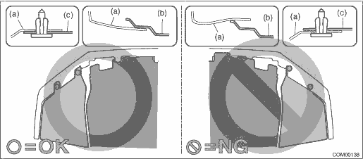
• Before installing the bumper face, match the claws on the bracket - front bumper with the engaging position of flange section on the bumper face side. If the engaging position is not correct, the flange section may be broken or the clearance between fender panel and bumper face may not be uniform.
Tightening torque:
Front bumper-related parts: General Description > COMPONENT">
Under cover - front: 18 N·m (1.84 kgf-m, 13.3 ft-lb)
3. Install each part in the reverse order of removal.
4. Adjust the headlight beam and fog light beam.
• Adjust the headlight beam. Headlight Assembly > ADJUSTMENT">
• Adjust the fog light beam. (Model with fog light) Front Fog Light Assembly > ADJUSTMENT">
 Front bumper
...
 Repair
EXTERIOR/INTERIOR TRIM > Front BumperREPAIR1. COATING METHOD FOR PP BUMPERProcess No.Process nameJob contents1Bumper installationPlace the bumper on a paint worktable as required. Use the paint wor ...
Other materials:
Electrical component location Location
INSTRUMENTATION/DRIVER INFO (DIAGNOSTICS) > Electrical Component LocationLOCATION(1)Combination meter(2)MFD(3)Data link connector ...
Dtc b28a1 eyesight communication(ecm)
EyeSight (DIAGNOSTICS) > Diagnostic Procedure with Diagnostic Trouble Code (DTC)DTC B28A1 EyeSight COMMUNICATION(ECM)Detected when the engine control module (ECM) detects the malfunction of stereo camera, or when the stereo camera or ECM is assembled incorrectly.DTC DETECTING CONDITION:• De ...
Auto Vehicle Hold indicator light
CAUTION
If the Auto Vehicle Hold indicator light in your Subaru Ascent does not activate
after selecting "Auto Vehicle Hold (AVH)", this may indicate a potential issue with
the electronic parking brake system. In such cases, the system may not function
as intended, and it is recomme ...
