Subaru Crosstrek Service Manual: Removal
CONTROL SYSTEMS > MT Gear Shift Lever
REMOVAL
1. Disconnect the ground cable from battery. NOTE">
NOTE:
For model with battery sensor, disconnect the ground terminal from battery sensor.
2. Remove the console box. Console Box > REMOVAL">
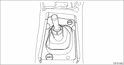
3. Remove the gear shift knob and remove the cover - shift lever.
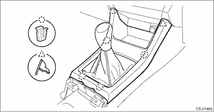
4. Remove the panel center LWR LH and RH. Console Box > REMOVAL">
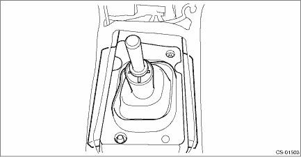
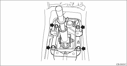
5. Remove the clamp.
6. Remove the boot and insulator assembly.
7. Remove the harness clamp from the plate COMPL.
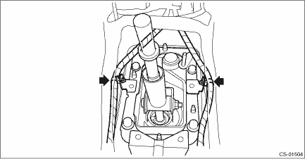
8. Remove the plate COMPL from the vehicle body.
9. Lift up the vehicle.
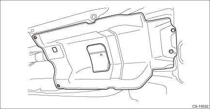
10. Remove the center exhaust pipe. Center Exhaust Pipe > REMOVAL">
11. Remove the center exhaust cover.
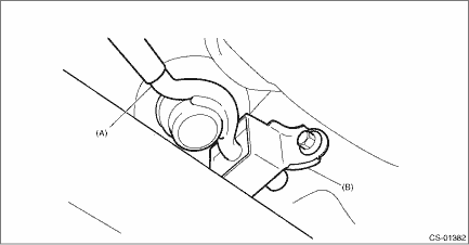
12. Remove the stay from the shift bracket.
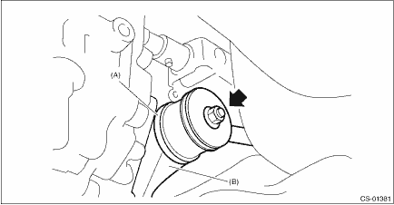
(A) | Stay |
(B) | Shift bracket |
13. Remove the rod from joint.
(A) | Stay |
(B) | Rod |
14. Remove the cushion rubber from the vehicle body.
(A) | Stay |
(B) | Cushion rubber |
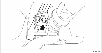
15. Extract the spring pin and remove the joint.
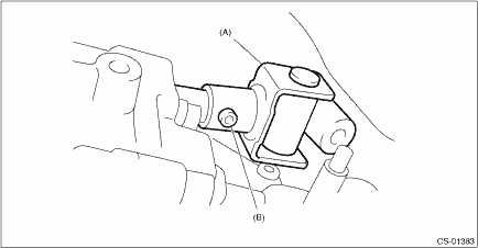
(A) | Joint |
(B) | Spring pin |
16. Lower the vehicle.
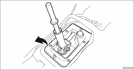
17. Remove the gear shift lever.
 Assembly
CONTROL SYSTEMS > MT Gear Shift LeverASSEMBLYNOTE:• Clean all the parts before assembly.• Apply NIGTIGHT LYW No. 2 grease or equivalent to each part. General Description > COMPONENT ...
 Disassembly
CONTROL SYSTEMS > MT Gear Shift LeverDISASSEMBLY1. Remove the lock wires.(A)Lock wire2. Remove the rod from gear shift lever.(A)Rod(B)Lever(C)Stay3. Separate the rod and inner boot.4. Remove the sn ...
Other materials:
Base display audio set (if equipped)
Power/VOLUME knob
Eject button
AUDIO/TUNE knob
HOME button
APPS button
Display
SEEK/TRACK buttons
The audio set will operate only when the
ignition switch is in the "ACC" or "ON"
position.
Power and audio controls: refer to
"Basic operation"
SUBARU STARLINK (if equipp ...
Using the Driver Monitoring System
User recognition
When a driver profile is registered, the Subaru Ascent utilizes facial recognition
technology to automatically identify the driver and apply personalized settings.
1. When the driver's door is opened while the push-button ignition switch is
OFF, the user recognition in ...
Dtc p2610 ecm/pcm engine off timer performance
ENGINE (DIAGNOSTICS)(H4DO) > Diagnostic Procedure with Diagnostic Trouble Code (DTC)DTC P2610 ECM/PCM ENGINE OFF TIMER PERFORMANCEDTC DETECTING CONDITION:Detected when two consecutive driving cycles with fault occur.CAUTION:After servicing or replacing faulty parts, perform Clear Memory Mode Cle ...
