Subaru Crosstrek Service Manual: Assembly
CONTROL SYSTEMS > MT Gear Shift Lever
ASSEMBLY
NOTE:
• Clean all the parts before assembly.
• Apply NIGTIGHT LYW No. 2 grease or equivalent to each part. General Description > COMPONENT">
1. Mount the bushing and cushion rubber to the stay.
(A) | Bushing |
(B) | Stay |
(C) | Cushion rubber |
2. Install the bushing and spacer to boss.
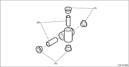
(A) | Bushing |
(B) | Spacer |
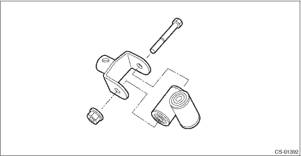
3. Install the boss to the joint.
NOTE:
Use a new self-locking nut.
Tightening torque:
12 N·m (1.2 kgf-m, 8.9 ft-lb)
4. Install the snap ring to gear shift lever and install the bushing.
NOTE:
Apply grease to the bushing.
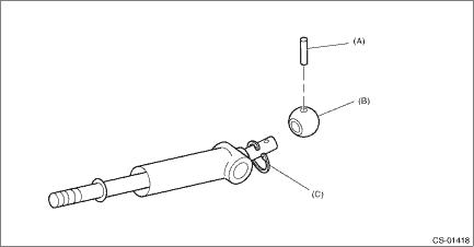
(A) | Spring pin |
(B) | Bushing |
(C) | Snap ring |
5. Apply grease to the bushing and O-ring, and then install to gear shift lever.
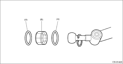
(A) | O-ring |
(B) | Bushing |
6. Apply sufficient grease into boss, and then install the gear shift lever to the stay.
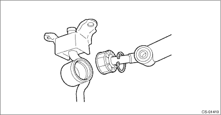
7. Install the snap ring.
(A) | Snap ring |
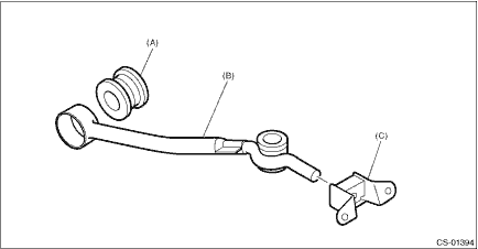
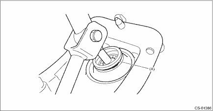
8. Insert the gear shift lever and rod into boot hole.
9. Install the rod.
NOTE:
Use a new self-locking nut.
Tightening torque:
12 N·m (1.2 kgf-m, 8.9 ft-lb)
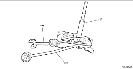
(A) | Rod |
(B) | Lever |
(C) | Stay |
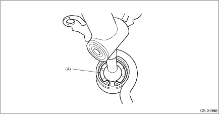
10. Install the lock wire.
NOTE:
Use a new lock wire.
(A) | Lock wire |
NOTE:
• Install the lock wire to the stay groove.
• Bend the extra wire to the same direction of lock wire winding.
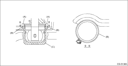
(A) | Inner boot |
(B) | Lock wire |
(C) | Stay |

 Removal
CONTROL SYSTEMS > MT Gear Shift LeverREMOVAL1. Disconnect the ground cable from battery. NOTE">NOTE:For model with battery sensor, disconnect the ground terminal from battery sensor.2. Rem ...
Other materials:
Removal
MECHANICAL(H4DO) > Timing Chain AssemblyREMOVAL1. TIMING CHAIN RHNOTE:When replacing a single part, perform the work with the engine assembly installed to body.1. Remove the chain cover. Chain Cover > REMOVAL">2. Using ST and by turning the crankshaft, align the alignment marks of cra ...
Security system Wiring diagram
WIRING SYSTEM > Security SystemWIRING DIAGRAM1. WITHOUT PUSH BUTTON START2. WITH PUSH BUTTON START ...
Removal
MANUAL TRANSMISSION AND DIFFERENTIAL(5MT) > Front Differential AssemblyREMOVAL1. Remove the manual transmission assembly from the vehicle. Manual Transmission Assembly > REMOVAL">2. Remove the transfer case together with the extension case assembly. Transfer Case and Extension Case A ...
