Subaru Crosstrek Service Manual: Dtc b1572 imm circuit except antenna circuit
IMMOBILIZER (DIAGNOSTICS) > Diagnostic Procedure with Diagnostic Trouble Code (DTC)
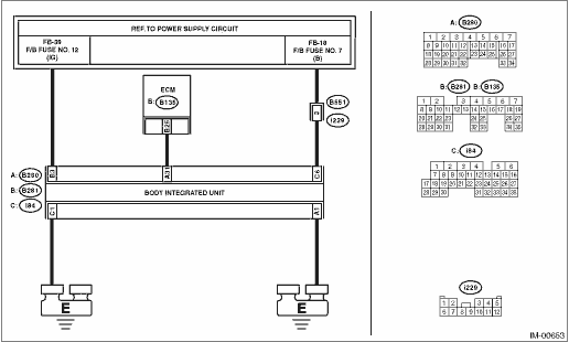
DTC B1572 IMM CIRCUIT EXCEPT ANTENNA CIRCUIT
DTC detecting condition:
Communication failure between body integrated unit and ECM
CAUTION:
When the body integrated unit is replaced, registration of the immobilizer system is required. For details, refer to the “REGISTRATION MANUAL FOR IMMOBILIZER” provided as a separate volume.
Wiring diagram:
Immobilizer system Immobilizer System > WIRING DIAGRAM">
| STEP | CHECK | YES | NO |
1.CHECK GROUNDING POINT.
Check the grounding point of the engine ground and chassis ground.
Are there any loose connections, any foreign objects caught in the ground lines or contact surface, or any fluid stains?
Remove the foreign matters, and tighten to the specified torque. Then start the engine, and check that the fault was removed. Check DTC Read Diagnostic Trouble Code (DTC)">, and when DTC B1572 is still displayed, Diagnostic Procedure with Diagnostic Trouble Code (DTC) > DTC B1572 IMM CIRCUIT EXCEPT ANTENNA CIRCUIT">Go to Step 2.
Diagnostic Procedure with Diagnostic Trouble Code (DTC) > DTC B1572 IMM CIRCUIT EXCEPT ANTENNA CIRCUIT">Go to Step 2.
2.CHECK FUSE.
1) Turn the ignition switch to OFF.
2) Check the fuse.
Is there any fault?
Replace the fuse. If the fuse blows out easily, repair the short circuit to power supply in harness between the battery and body integrated unit.
Diagnostic Procedure with Diagnostic Trouble Code (DTC) > DTC B1572 IMM CIRCUIT EXCEPT ANTENNA CIRCUIT">Go to Step 3.
3.CHECK CURRENT DATA.
Confirm the current data «BATT voltage (control)» display of body integrated unit. Read Current Data">
Is the display 10 V or more?
Diagnostic Procedure with Diagnostic Trouble Code (DTC) > DTC B1572 IMM CIRCUIT EXCEPT ANTENNA CIRCUIT">Go to Step 4.
Diagnostic Procedure with Diagnostic Trouble Code (DTC) > DTC B1572 IMM CIRCUIT EXCEPT ANTENNA CIRCUIT">Go to Step 5.
4.CHECK CURRENT DATA.
Check the current data «Voltage of IGN» display of body integrated unit. Read Current Data">
Is the display 10 V or more?
Diagnostic Procedure with Diagnostic Trouble Code (DTC) > DTC B1572 IMM CIRCUIT EXCEPT ANTENNA CIRCUIT">Go to Step 7.
Diagnostic Procedure with Diagnostic Trouble Code (DTC) > DTC B1572 IMM CIRCUIT EXCEPT ANTENNA CIRCUIT">Go to Step 6.
5.CHECK BODY INTEGRATED UNIT BATTERY POWER SUPPLY CIRCUIT.
1) Turn the ignition switch to OFF.
2) Disconnect the body integrated unit connector.
3) Measure the voltage between body integrated unit connector and chassis ground.
Connector & terminal
(i84) No. 6 (+) — Chassis ground (−):
Is the voltage 10 V or more?
Diagnostic Procedure with Diagnostic Trouble Code (DTC) > DTC B1572 IMM CIRCUIT EXCEPT ANTENNA CIRCUIT">Go to Step 6.
Repair the open or short circuit of harness between the body integrated unit connector and fuse.
6.CHECK BODY INTEGRATED UNIT IGN POWER SUPPLY CIRCUIT.
1) Turn the ignition switch to ON.
2) Measure the voltage between the body integrated unit connector terminal and chassis ground.
Connector & terminal
(B281) No. 3 (+) — Chassis ground (−):
Is the voltage 10 V or more?
Diagnostic Procedure with Diagnostic Trouble Code (DTC) > DTC B1572 IMM CIRCUIT EXCEPT ANTENNA CIRCUIT">Go to Step 7.
Repair the open or short circuit of harness between the body integrated unit connector and ignition switch.
7.CHECK BODY INTEGRATED UNIT GROUND CIRCUIT (OPEN CIRCUIT).
1) Turn the ignition switch to OFF.
2) Measure the resistance between body integrated unit connector and chassis ground.
Connector & terminal
(B280) No. 1 — Chassis ground:
(i84) No. 1 — Chassis ground:
Is the resistance less than 10 ??
Diagnostic Procedure with Diagnostic Trouble Code (DTC) > DTC B1572 IMM CIRCUIT EXCEPT ANTENNA CIRCUIT">Go to Step 8.
Repair the open circuit of harness between the body integrated unit connector and chassis ground.
8.CHECK GROUND CIRCUIT FOR ECM (OPEN CIRCUIT).
1) Disconnect the ECM connector.
2) Measure the resistance between the ECM connector and engine ground.
Connector & terminal
(B134) No. 3 — Engine ground:
(B134) No. 4 — Engine ground:
(B136) No. 1 — Engine ground:
(B136) No. 2 — Engine ground:
(B136) No. 3 — Engine ground:
Is the resistance less than 10 ??
Diagnostic Procedure with Diagnostic Trouble Code (DTC) > DTC B1572 IMM CIRCUIT EXCEPT ANTENNA CIRCUIT">Go to Step 9.
Repair the open circuit in harness between ECM connector and chassis ground.
9.CHECK HARNESS (OPEN CIRCUIT) BETWEEN BODY INTEGRATED UNIT AND ECM.
1) Disconnect the ECM connector.
2) Measure the resistance between the body integrated unit connector and ECM connector.
Connector & terminal
(B280) No. 31 — (B135) No. 25:
Is the resistance less than 10 ??
Diagnostic Procedure with Diagnostic Trouble Code (DTC) > DTC B1572 IMM CIRCUIT EXCEPT ANTENNA CIRCUIT">Go to Step 10.
Repair the open circuit of harness between the body integrated unit connector and ECM.
10.CHECK COMMUNICATION LINE HARNESS (SHORT CIRCUIT TO POWER SUPPLY).
1) Disconnect the body integrated unit connector.
2) Turn the ignition switch to ON.
3) Measure the voltage between ECM connector and engine ground.
Connector & terminal
(B135) No. 25 (+) — Engine ground (−):
Is the voltage 6 V or more?
Repair the short circuit to power supply in harness between body integrated unit connector and ECM connector.
Diagnostic Procedure with Diagnostic Trouble Code (DTC) > DTC B1572 IMM CIRCUIT EXCEPT ANTENNA CIRCUIT">Go to Step 11.
11.CHECK COMMUNICATION CIRCUIT HARNESS (SHORT CIRCUIT TO GROUND).
1) Turn the ignition switch to OFF.
2) Measure the resistance between the ECM connector and engine ground.
Connector & terminal
(B135) No. 25 — Engine ground:
Is the resistance less than 10 ??
Repair the ground short circuit of harness between body integrated unit connector and ECM connector.
Diagnostic Procedure with Diagnostic Trouble Code (DTC) > DTC B1572 IMM CIRCUIT EXCEPT ANTENNA CIRCUIT">Go to Step 12.
12.CHECK ECM.
1) Replace the ECM. (Do not perform ECM registration.) Engine Control Module (ECM)">
2) Connect all connectors.
3) Turn the ignition switch to ON.
4) Wait for 5 seconds.
5) Read DTC of engine. Read Diagnostic Trouble Code (DTC)">
Is DTC B1572 displayed?
Replace the body integrated unit. Body Integrated Unit">
Register the ECM. Refer to the “REGISTRATION MANUAL FOR IMMOBILIZER” provided as a separate volume.
 Dtc b1570 antenna
IMMOBILIZER (DIAGNOSTICS) > Diagnostic Procedure with Diagnostic Trouble Code (DTC)DTC B1570 ANTENNADTC detecting condition:Faulty antennaCAUTION:When the body integrated unit is replaced, registra ...
 Dtc b1574 key communication
IMMOBILIZER (DIAGNOSTICS) > Diagnostic Procedure with Diagnostic Trouble Code (DTC)DTC B1574 KEY COMMUNICATIONDTC DETECTING CONDITION:Communication failure between key and body integrated unitCAUTI ...
Other materials:
Installation
BRAKE > Brake HoseINSTALLATION1. FRONT BRAKE HOSE1. Secure the brake hose to strut mount.Tightening torque:Brake hose: 33 N·m (3.36 kgf-m, 24.3 ft-lb)2. Connect the brake hose to the front caliper body assembly using a new gasket.Tightening torque:Union bolt: 26 N·m (2.65 kgf-m, 19. ...
Check adaptive cruise control indicator light/constant speed cruise control indicator light and cruise set indicator light
EyeSight (DIAGNOSTICS) > Diagnostics with PhenomenonCHECK ADAPTIVE CRUISE CONTROL INDICATOR LIGHT/CONSTANT SPEED CRUISE CONTROL INDICATOR LIGHT AND CRUISE SET INDICATOR LIGHTTROUBLE SYMPTOM:Adaptive cruise control or conventional cruise control can be set, but adaptive cruise control indicator li ...
Removal
SECURITY AND LOCKS > Rear Inner RemoteREMOVAL1. Disconnect the ground cable from battery. NOTE">2. Remove the trim panel - rear door. Door Trim > REMOVAL">3. Remove the screw, and remove the remote assembly - door. ...
