Subaru Crosstrek Service Manual: Dtc b1570 antenna
IMMOBILIZER (DIAGNOSTICS) > Diagnostic Procedure with Diagnostic Trouble Code (DTC)
DTC B1570 ANTENNA
DTC detecting condition:
Faulty antenna
CAUTION:
When the body integrated unit is replaced, registration of the immobilizer system is required. For details, refer to the “REGISTRATION MANUAL FOR IMMOBILIZER” provided as a separate volume.
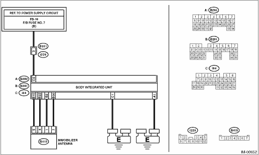
Wiring diagram:
Immobilizer system Immobilizer System > WIRING DIAGRAM">
| STEP | CHECK | YES | NO |
1.CHECK BODY INTEGRATED UNIT POWER SUPPLY CIRCUIT.
1) Turn the ignition switch to OFF.
2) Disconnect the connector from body integrated unit.
3) Measure the voltage between the body integrated unit connector terminal and chassis ground.
Connector & terminal
(i84) No. 6 (+) — Chassis ground (−):
Is the voltage 10 V or more?
Diagnostic Procedure with Diagnostic Trouble Code (DTC) > DTC B1570 ANTENNA">Go to Step 2.
Check the harness for open or short circuit between body integrated unit and fuse.
2.CHECK BODY INTEGRATED UNIT GROUND CIRCUIT (OPEN CIRCUIT).
Measure the resistance between the body integrated unit connector terminal and chassis ground.
Connector & terminal
(B280) No. 1 — Chassis ground:
(i84) No. 1 — Chassis ground:
Is the resistance less than 10 ??
Diagnostic Procedure with Diagnostic Trouble Code (DTC) > DTC B1570 ANTENNA">Go to Step 3.
Repair the open circuit of the body integrated unit ground circuit.
3.CHECK ANTENNA POWER SUPPLY CIRCUIT.
1) Connect the connector to body integrated unit.
2) Disconnect the connector from the antenna.
3) Insert the ignition key into the key cylinder, then measure the voltage between the antenna connector terminal and the chassis ground.
Connector & terminal
(B415) No. 1 (+) — Chassis ground (−):
Is the voltage 5±0.5 V approx. 200 ms after inserting the ignition key into the key cylinder? And then, does the voltage return to 0 V within 2 s?
Diagnostic Procedure with Diagnostic Trouble Code (DTC) > DTC B1570 ANTENNA">Go to Step 5.
Diagnostic Procedure with Diagnostic Trouble Code (DTC) > DTC B1570 ANTENNA">Go to Step 4.
4.CHECK ANTENNA POWER SUPPLY CIRCUIT (OPEN).
1) Disconnect the connector from body integrated unit.
2) Measure the resistance of body integrated unit connector terminal and antenna connector terminal.
Connector & terminal
(B281) No. 2 — (B415) No. 1:
Is the resistance less than 10 ??
Replace the body integrated unit. Body Integrated Unit">
Repair the harness or connector between body integrated unit and antenna.
5.CHECK ANTENNA GROUND CIRCUIT (SHORT CIRCUIT TO GROUND).
Measure the resistance between antenna connector terminal and chassis ground.
Connector & terminal
(B415) No. 7 — Chassis ground:
Is the resistance less than 10 ??
Diagnostic Procedure with Diagnostic Trouble Code (DTC) > DTC B1570 ANTENNA">Go to Step 7.
Diagnostic Procedure with Diagnostic Trouble Code (DTC) > DTC B1570 ANTENNA">Go to Step 6.
6.CHECK ANTENNA GROUND CIRCUIT (OPEN).
1) Disconnect the connector from body integrated unit.
2) Measure the resistance between the body integrated unit connector terminal and antenna connector terminal.
Connector & terminal
(B281) No. 30 — (B415) No. 7:
Is the resistance less than 10 ??
Replace the body integrated unit. Body Integrated Unit">
Repair the harness or connector between body integrated unit and antenna.
7.CHECK ANTENNA COMMUNICATION CIRCUIT (OPEN).
Measure the resistance of body integrated unit connector terminal and antenna connector terminal.
Connector & terminal
(B281) No. 10 — (B415) No. 5:
(B281) No. 22 — (B415) No. 4:
Is the resistance less than 10 ??
Diagnostic Procedure with Diagnostic Trouble Code (DTC) > DTC B1570 ANTENNA">Go to Step 8.
Repair the harness or connector between body integrated unit and antenna.
8.CHECK ANTENNA.
1) Replace the immobilizer antenna. Immobilizer Antenna">
2) Insert the ignition key in the ignition switch. (OFF or ACC)
3) Perform the Clear Memory Mode. Clear Memory Mode">
4) Read the DTC of the body integrated unit. Read Diagnostic Trouble Code (DTC)">
Is DTC B1411 detected?
Replace the body integrated unit. Body Integrated Unit">
Antenna has a failure.
 Dtc b1411 immobilizer antenna
IMMOBILIZER (DIAGNOSTICS) > Diagnostic Procedure with Diagnostic Trouble Code (DTC)DTC B1411 IMMOBILIZER ANTENNANOTE:Refer to DTC B1570 for diagnostic procedure. Diagnostic Procedure with Diagnost ...
 Dtc b1572 imm circuit except antenna circuit
IMMOBILIZER (DIAGNOSTICS) > Diagnostic Procedure with Diagnostic Trouble Code (DTC)DTC B1572 IMM CIRCUIT EXCEPT ANTENNA CIRCUITDTC detecting condition:Communication failure between body integrated ...
Other materials:
Removal
LIGHTING SYSTEM > License Plate LightREMOVAL1. Disconnect the ground cable from battery. NOTE">2. Remove the license plate light.(1) Release the claws and pull out the license plate light.(2) Disconnect the connector and remove the bulb socket and bulb from the license plate light.CAUTIO ...
Viewing range on the screen
CAUTION
The range that can be viewed with
the rear view camera is limited.
Always be sure to check with your
eyes when moving backward and
proceed slowly.
Range of view
Range of view
Image from camera
The area from the rear end of the bumper
can be viewed. Areas at both ends ...
Assembly
SEATS > Front SeatASSEMBLYCAUTION:• Do not confuse the harness routing of the side airbag harness and the seat belt inner - front harness, etc. Assembling with harnesses improperly routed may cause the harness to get caught and short out.• If the flat mat hook of the frame assembly - ...
