Subaru Crosstrek Service Manual: Disassembly
CONTROL SYSTEMS > MT Gear Shift Lever
DISASSEMBLY
1. Remove the lock wires.
(A) | Lock wire |
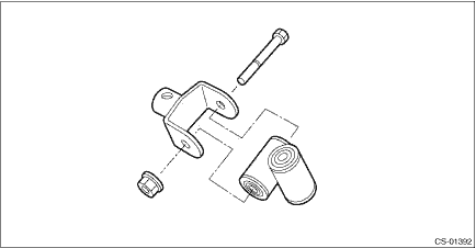
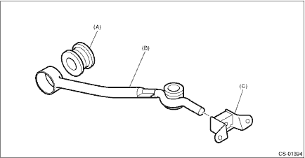
2. Remove the rod from gear shift lever.
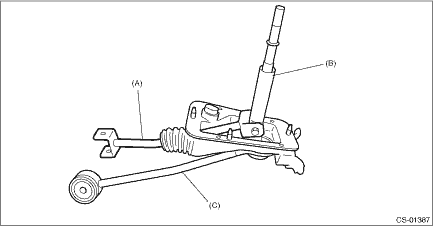
(A) | Rod |
(B) | Lever |
(C) | Stay |
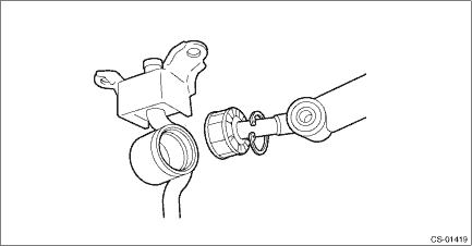
3. Separate the rod and inner boot.
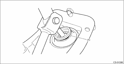
4. Remove the snap ring from the stay.
(A) | Snap ring |
5. Separate the gear shift lever and the stay.
6. Remove the boot and bushing from the gear shift lever.
(A) | O-ring |
(B) | Bushing |
7. Remove the spring pin, and then remove the bushing and snap ring.
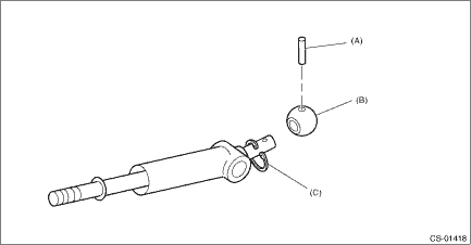
(A) | Spring pin |
(B) | Bushing |
(C) | Snap ring |
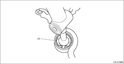
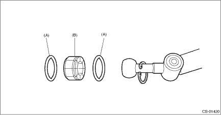
8. Remove the boss from the joint.
9. Remove the bushing and spacer from the boss.
(A) | Bushing |
(B) | Spacer |
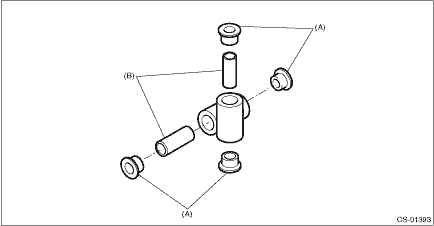
10. Remove the bushing and cushion rubber from the stay.
(A) | Bushing B |
(B) | Stay |
(C) | Cushion rubber |
 Removal
CONTROL SYSTEMS > MT Gear Shift LeverREMOVAL1. Disconnect the ground cable from battery. NOTE">NOTE:For model with battery sensor, disconnect the ground terminal from battery sensor.2. Rem ...
 Inspection
CONTROL SYSTEMS > MT Gear Shift LeverINSPECTION1. Check the parts (bushing, cushion rubber, spacer, boot, stay and rod, etc.) for deformation, damage and wear. If necessary, correct or replace faul ...
Other materials:
Assembly
DRIVE SHAFT SYSTEM > Front Drive ShaftASSEMBLY1. Roll up a thick piece of paper to a size where the shaft can pass through, and affix with tape to form a cylinder.2. Attach a new O-ring on this cylinder.CAUTION:• Always use a new O-ring.• Be careful that the O-ring does not become scr ...
Roof tent
WARNING
Installing a roof tent on the Subaru Ascent increases the overall weight positioned
above the vehicle’s center of gravity, which can negatively influence handling,
braking efficiency, and rollover resistance. Under no circumstances should the Subaru
Ascent be driven if the total ...
Cooling fan, hose and connections
Your vehicle employs an electric cooling
fan which is thermostatically controlled to
operate when the engine coolant reaches
a specific temperature.
If the radiator cooling fan does not operate
even when the coolant temperature high
warning light blinks or illuminates in RED,
the cooling fa ...
