Subaru Crosstrek Service Manual: Malfunction indicator light remains blinking
ENGINE (DIAGNOSTICS)(H4DO) > Malfunction Indicator Light
MALFUNCTION INDICATOR LIGHT REMAINS BLINKING
Diagnosis:
The delivery (test) mode fuse circuit is short-circuited to ground.
Trouble symptom:
Malfunction indicator light blinks when delivery (test) mode fuse is not connected.
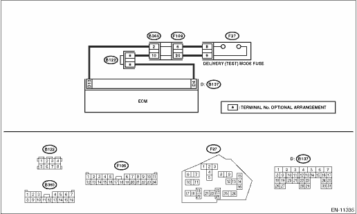
Wiring diagram:
Engine electrical system Engine Electrical System">
| STEP | CHECK | YES | NO |
1.CHECK DELIVERY (TEST) MODE CONNECTOR.
1) Check the delivery (test) mode fuse is removed.
2) Turn the ignition switch to ON.
Does the malfunction indicator light blink?
Malfunction Indicator Light > MALFUNCTION INDICATOR LIGHT REMAINS BLINKING">Go to Step 2.
System is normal.
NOTE:
Malfunction indicator light blinks at a cycle of 3 Hz when delivery (test) mode fuse is attached.
2.CHECK HARNESS BETWEEN ECM AND DELIVERY (TEST) MODE FUSE.
1) Turn the ignition switch to OFF.
2) Disconnect the connector from ECM.
3) Measure the resistance between ECM connector and chassis ground.
Connector & terminal
(B137) No. 13 — Chassis ground:
Is the resistance 1 M? or more?
Replace the ECM. Engine Control Module (ECM)">
Repair the short circuit to ground in the harness between the ECM connector and delivery (test) mode fuse.
 Procedure
ENGINE (DIAGNOSTICS)(H4DO) > Malfunction Indicator LightPROCEDURE1. Activation of malfunction indicator light Malfunction Indicator Light > ACTIVATION OF MALFUNCTION INDICATOR LIGHT">&d ...
 Activation of malfunction indicator light
ENGINE (DIAGNOSTICS)(H4DO) > Malfunction Indicator LightACTIVATION OF MALFUNCTION INDICATOR LIGHT1. When the ignition switch is turned to ON (engine OFF), the malfunction indicator light (A) in the ...
Other materials:
Dtc u0122 lost communication with vehicle dynamics control module
POWER ASSISTED SYSTEM (POWER STEERING) (DIAGNOSTICS) > Diagnostic Procedure with Diagnostic Trouble Code (DTC)DTC U0122 LOST COMMUNICATION WITH VEHICLE DYNAMICS CONTROL MODULENOTE:Refer to “LAN SYSTEM” for diagnostic procedure. Basic Diagnostic Procedure"> ...
Check eyesight steering switch
EyeSight (DIAGNOSTICS) > Diagnostics with PhenomenonCHECK EyeSight STEERING SWITCHTrouble symptom:• Cruise control cannot be set. (Cancelled immediately.)• Cruise control cannot be released.Wiring diagram:EyeSight System EyeSight System > WIRING DIAGRAM">STEPCHECKYESNO1.CH ...
Dtc b16fa door sensor lh recognition error
AIRBAG SYSTEM (DIAGNOSTICS) > Diagnostic Chart with Trouble CodeDTC B16FA DOOR SENSOR LH RECOGNITION ERRORDiagnosis start condition:Ignition voltage is 10 V to 16 V.DTC detecting condition:• Front door impact sensor (LH) is misinstalled.• Airbag control module is faulty.CAUTION:Before ...
