Subaru Crosstrek Service Manual: Activation of malfunction indicator light
ENGINE (DIAGNOSTICS)(H4DO) > Malfunction Indicator Light
ACTIVATION OF MALFUNCTION INDICATOR LIGHT
1. When the ignition switch is turned to ON (engine OFF), the malfunction indicator light (A) in the combination meter illuminates.
NOTE:
If the malfunction indicator light does not illuminate, perform diagnostics of the malfunction indicator light circuit or the combination meter circuit. Malfunction Indicator Light > MALFUNCTION INDICATOR LIGHT DOES NOT COME ON">
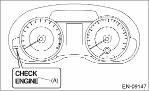
2. After starting the engine, the malfunction indicator light goes out. If it does not go off, any of the engine and emission control system has malfunction.
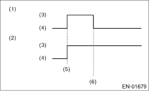
(1) | No faulty |
(2) | Trouble occurs |
(3) | ON |
(4) | OFF |
(5) | Ignition switch ON |
(6) | Engine start |
3. If the diagnostic system detects a misfire which could damage the catalyst, the malfunction indicator light will blink at a cycle of 1 Hz.
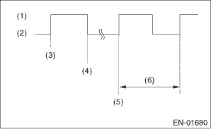
(1) | ON |
(2) | OFF |
(3) | Ignition switch ON |
(4) | Engine start |
(5) | Misfire start |
(6) | 1 second |
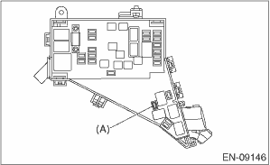
4. Install the delivery (test) mode fuse (A) with ignition switch to OFF.
CAUTION:
Do not use any fuses that are installed on the vehicle.
(1) When the ignition switch is turned to ON (engine OFF), the malfunction indicator light illuminates.
(2) After the engine starts, malfunction indicator light blinks in a cycle of 0.5 Hz. (During diagnosis)
(3) Malfunction indicator light blinks at a cycle of 3 Hz after diagnosis if there is no trouble. Malfunction indicator light illuminates if faulty.
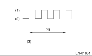
(1) | ON |
(2) | OFF |
(3) | Ignition switch ON |
(4) | 1 second |
 Malfunction indicator light remains blinking
ENGINE (DIAGNOSTICS)(H4DO) > Malfunction Indicator LightMALFUNCTION INDICATOR LIGHT REMAINS BLINKINGDiagnosis:The delivery (test) mode fuse circuit is short-circuited to ground.Trouble symptom:Malf ...
 Malfunction indicator light does not come on
ENGINE (DIAGNOSTICS)(H4DO) > Malfunction Indicator LightMALFUNCTION INDICATOR LIGHT DOES NOT COME ONTROUBLE SYMPTOM:When the ignition switch is turned to ON (engine OFF), malfunction indicator ligh ...
Other materials:
Under-floor storage compartment
CAUTION
While driving the Subaru Ascent, always ensure that the under-floor storage
compartment lid is securely closed. An open lid may become a hazard during sudden
braking or in the event of a collision.
Do not place flammable materials, pressurized containers, or corrosive
substanc ...
Dtc u0122 lost communication with vehicle dynamics control module
ENGINE (DIAGNOSTICS)(H4DO) > Diagnostic Procedure with Diagnostic Trouble Code (DTC)DTC U0122 LOST COMMUNICATION WITH VEHICLE DYNAMICS CONTROL MODULENOTE:For the diagnostic procedure, refer to LAN section. Basic Diagnostic Procedure">1. OUTLINE OF DIAGNOSISDetect malfunction of CAN commu ...
Dtc u1120 lost communication with autostart stop control module
KEYLESS ACCESS WITH PUSH BUTTON START SYSTEM (DIAGNOSTICS) > Diagnostic Procedure with Diagnostic Trouble Code (DTC)DTC U1120 LOST COMMUNICATION WITH AUTOSTART STOP CONTROL MODULEDetected when CAN data from hybrid system or Auto Start Stop CM is abnormal.NOTE:Perform the diagnosis for LAN system. ...
