Subaru Crosstrek Service Manual: Installation
VEHICLE DYNAMICS CONTROL (VDC) > VDC Control Module and Hydraulic Control Unit (VDCCM&H/U)
INSTALLATION
1. MODELS WITHOUT EyeSight
CAUTION:
• When installing the VDCCM&H/U to the bracket - hydraulic unit, make sure that there is no oil adhered to the bolts and the threads of VDCCM&H/U. If the oil is adhered, degrease it carefully before tightening.
• Connect the VDCCM&H/U connector securely.
• When installing the VDCCM&H/U, replace the damper - hydraulic unit, spacer and nut with new parts.
1. Install the VDC control module & hydraulic control unit (VDCCM&H/U) in the reverse order of removal.
Tightening torque:
Refer to “COMPONENT” of “General Description”. General Description > COMPONENT">
2. Install the air intake boot. Air Intake Boot > INSTALLATION">
3. Connect the battery ground terminal. NOTE">
4. Bleed air from the brake system. Air Bleeding">
5. Perform parameter confirmation, selection, and registration.
NOTE:
• When the VDCCM&H/U is replaced with a new part, be sure to perform the selection • registration operation.
• When the registration has not been performed, the DTC code “Parameter selection error” is detected together with the ABS/EBD/VDC warning light illumination.
(1) Check that the applied model and grade of the relevant vehicle are included. Subaru Select Monitor > OPERATION">
(2) If the applied model and grade of the target vehicle are not included, perform parameter selection and registration. Subaru Select Monitor > OPERATION">
6. Perform “VDC sensor midpoint setting mode”. VDC Control Module and Hydraulic Control Unit (VDCCM&H/U) > ADJUSTMENT">
2. MODELS WITH EyeSight
CAUTION:
• When the VDCCM&H/U components are removed, be sure to perform the installation according to the following procedures to prevent fluid leakage.
• When installing the VDCCM&H/U to the bracket - hydraulic unit, make sure that there is no oil adhered to the bolts and the threads of VDCCM&H/U. If the oil is adhered, degrease it carefully before tightening.
• Be careful not to deform the bracket - hydraulic unit for hose assembly.
• Connect the VDCCM&H/U connector securely.
1. Install the VDCCM&H/U.
NOTE:
Refer to the following figure for tightening torque.
(1) Set the VDCCM&H/U (a) to the bracket - hydraulic unit (b).
(2) Set the hose assembly (c) to the bracket - hydraulic unit (b).
(3) Set pipe A (d) and pipe B (e), and temporarily tighten the flare nuts.
(4) Tighten the VDCCM&H/U (a) and the bracket - hydraulic unit (b).
(5) Tighten the hose assembly (c) and the bracket - hydraulic unit (b).
(6) Tighten pipe A (d) and pipe B (e).
(7) Set the center pipes (f) to hose assembly (c), and temporarily tighten the flare nuts.
(8) Install the hose assembly (c) to the vehicle body.
(9) Tighten the flare nuts of the center pipes (f).
(10) Install the brake pipes (g).
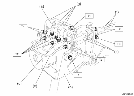
Tightening torque:
T1: 7.5 N·m (0.8 kgf-m, 5.5 ft-lb)
T2: 15 N·m (1.5 kgf-m, 11.1 ft-lb)
T3: 18 N·m (1.8 kgf-m, 13.3 ft-lb)
T4: 19 N·m (1.9 kgf-m, 14.0 ft-lb)
2. Connect the VDCCM&H/U connector.
3. Install the air intake boot. Air Intake Boot > INSTALLATION">
4. Connect the battery ground terminal. NOTE">
5. Bleed air from the brake system. Air Bleeding">
6. Perform parameter confirmation, selection, and registration.
NOTE:
• When the VDCCM&H/U is replaced with a new part, be sure to perform the selection · registration operation.
• When the registration has not been performed, the DTC code “Parameter selection error” is detected together with the ABS/EBD/VDC warning light illumination.
(1) Check that the applied model and grade of the relevant vehicle are included. Subaru Select Monitor > OPERATION">
(2) If the applied model and grade of the target vehicle are not included, perform parameter selection and registration. Subaru Select Monitor > OPERATION">
7. Perform the following VDC setting mode.
• Neutral of Steering Angle Sensor & Lateral G Sensor 0 point setting VDC Control Module and Hydraulic Control Unit (VDCCM&H/U) > ADJUSTMENT">
• Longitudinal G sensor & lateral G sensor 0 point setting VDC Control Module and Hydraulic Control Unit (VDCCM&H/U) > ADJUSTMENT">
 Inspection
VEHICLE DYNAMICS CONTROL (VDC) > VDC Control Module and Hydraulic Control Unit (VDCCM&H/U)INSPECTION1. Check the identification (a) of the VDC control module & hydraulic control unit (VDCCM ...
 Removal
VEHICLE DYNAMICS CONTROL (VDC) > VDC Control Module and Hydraulic Control Unit (VDCCM&H/U)REMOVAL1. MODELS WITHOUT EyeSight1. Disconnect the ground cable from battery. NOTE">2. Remove ...
Other materials:
Regarding access key
CAUTION
If the access key is dropped, the
integrated mechanical key inside
may become loose. Be careful not
to lose the mechanical key.
NOTE
The access key is always communicating
with the vehicle and is continuously
using the battery. Although
the life of the battery varies depending
on t ...
Certification for remote keyless entry system
U.S.-spec. models
FCC ID: CWTWB1U811
FCC ID: CWTWD1U781
CAUTION
FCC WARNING
Changes or modifications not expressly
approved by the party responsible
for compliance could void
the user's authority to operate the
equipment.
NOTE
This device complies with part 15 of the
FCC Rules. Operation ...
Tire pressure monitoring system (TPMS) (U.S.-spec. models)
Low tire pressure warning light (type A)
Low tire pressure warning light (type B)
The tire pressure monitoring system provides
the driver with a warning message
when tire pressure is severely low.
The tire pressure monitoring system will
activate only when the vehicle is driven at
s ...
