Subaru Crosstrek Service Manual: Installation
MECHANICAL(H4DO) > Crank Pulley
INSTALLATION
1. Degrease the press-fit section for the chain cover front oil seal, and install the front oil seal to the chain cover using ST.
CAUTION:
Do not apply fluid such as engine oil to the front oil seal and the chain cover; otherwise engine oil leakage may occur.
NOTE:
• Use a new front oil seal.
• When tapping the front oil seal in, protect the radiator fin with cardboards etc. so as not to damage the radiator fin by the plastic hammer.
| ST 41399FG020 | SPECIAL TOOL B |
Front oil seal press-fit position:
1+0 −1 mm (0.0039+0 −0.0039 in) position from chain cover end face
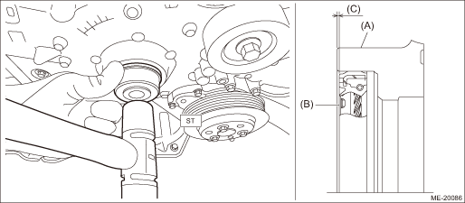
(A) | Chain cover | (B) | Oil seal | (C) | Front oil seal press-fit position (1+0 −1 mm (0.0039+0 −0.0039 in) position from chain cover end face) |
2. Clean the crankshaft thread using compressed air.
3. Apply engine oil to the crank pulley bolt seat and thread.
4. Install the crank pulley.
(1) Set the crank pulley to the chain cover.
NOTE:
• Use new O-rings.
• Install the crank pulley by aligning the crank pulley knock hole (A) and crank pulley boss knock pin (B).

(2) Use the ST to lock the crank pulley, and temporarily tighten the crank pulley bolt.
NOTE:
To prevent damaging ST1, attach the ST2 onto the ST1 as shown.
| ST1 18355AA000 | PULLEY WRENCH |
| ST2 18334AA000 | PULLEY WRENCH PIN SET |

| ST1 18355AA000 | PULLEY WRENCH |
| ST2 18334AA000 | PULLEY WRENCH PIN SET |
Tightening torque:
60 N·m (6.1 kgf-m, 44.3 ft-lb)

(3) Draw reference lines (A) and (B) using a marker to set the socket to the crank pulley bolt as shown in the figure.

(a) | When using 6-point socket | (b) | When using 12-point socket | ||
(4) Draw reference lines (A) and (B) on the crank pulley bolt using a marker as shown in the figure.

(5) Draw end line (C) on crank pulley using a marker at the same position as reference line (B) drawn on the crank pulley bolt in step (3).

(6) Use the ST to lock the crank pulley, and tighten the crank pulley bolt to the angle where reference line (A) and end line (C) are aligned.
NOTE:
It should be approx. 60° when reference line (A) and end line (C) are aligned.
| ST1 18355AA000 | PULLEY WRENCH |
| ST2 18334AA000 | PULLEY WRENCH PIN SET |
Tightening angle:
60°±5°

5. Install the V-belts. V-belt > INSTALLATION">
6. When working on the vehicle
NOTE:
When working on the vehicle, perform the following steps also.
(1) Install the radiator main fan & fan motor assembly and radiator sub fan & fan motor assembly. Radiator Main Fan and Fan Motor > INSTALLATION"> Radiator Sub Fan and Fan Motor > INSTALLATION">
 Removal
MECHANICAL(H4DO) > Crank PulleyREMOVALNOTE:When replacing a single part, perform the work with the engine assembly installed to body.1. When working on the vehicleNOTE:When working on the vehicle, ...
 Crank sprocket
...
Other materials:
Dtc b19f0 short in front p/t 2 rh
AIRBAG SYSTEM (DIAGNOSTICS) > Diagnostic Chart with Trouble CodeDTC B19F0 SHORT IN FRONT P/T 2 RHDiagnosis start condition:Ignition voltage is 10 V to 16 V.DTC detecting condition:• Lap seat belt pretensioner (RH) circuit is shorted.• Lap seat belt pretensioner (RH) is faulty.• ...
List of diagnostic trouble code (dtc) List
POWER ASSISTED SYSTEM (POWER STEERING) (DIAGNOSTICS) > List of Diagnostic Trouble Code (DTC)LISTDTCItemContent of diagnosisNoteNoneWithout DTCNormal Subaru Select Monitor > INSPECTION">“Assist limitation” is displayed in the current data «EPS operating condition».Assist l ...
Disassembly
CONTROL SYSTEMS > Select LeverDISASSEMBLY1. GRIP ASSY1. Remove the button assembly_AT.(A)Claw2. Remove the rod COMPL.2. AT SELECT LEVER ASSEMBLY1. Remove the spacer plate.2. Remove the gasket.3. Insert a flat tip screwdriver with a thin tip under the connector and disconnect the harness connector ...
