Subaru Crosstrek Service Manual: Inspection
CLUTCH SYSTEM > Clutch Switch
INSPECTION
1. CLUTCH START SWITCH
1. Perform the following inspections. If the clutch start switch does not operate normally, adjust the switch, and check it again. Clutch Switch > ADJUSTMENT">
• Make sure that engine does not start with clutch pedal not depressed.
• Make sure that engine starts with clutch pedal fully depressed.
2. When the clutch start switch does not operate normally even if it is adjusted, check the clutch start switch for continuity.
(1) Remove the clutch start switch. Clutch Switch > REMOVAL">
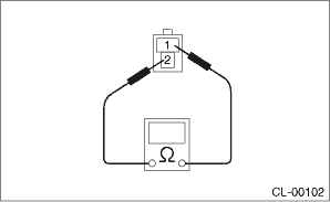
(2) Measure the resistance between terminal 1 and 2 of the switch. If the resistance is not at the standard value, replace the switch.
Condition | Terminal No. | Specified resistance |
ON | No. 1 — No. 2 | Less than 1 ? |
OFF | No. 1 — No. 2 | 1 M? or more |
(3) Check that the switch is turned on and off in dimension L.
Dimension L:
9 — 10 mm (0.35 — 0.39 in)
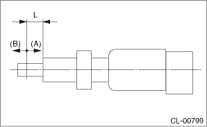
(A) | ON |
(B) | OFF |
(4) Install the clutch start switch. Clutch Switch > INSTALLATION">
2. CLUTCH SWITCH
1. Check the clutch switch for continuity.
(1) Disconnect the connector of clutch switch.
(2) Measure the resistance between terminal 1 and 2 of the switch. If the resistance is not within the specification, check the clutch stroke and installation condition, and check the clutch switch again.
Condition | Terminal No. | Specified resistance |
When clutch pedal is depressed | No. 1 — No. 2 | 1 M? or more |
When the clutch pedal is not depressed | No. 1 — No. 2 | Less than 1 ? |
2. When the clutch switch does not operate normally even if the clutch stroke and installation condition are normal, check the clutch switch for continuity.
(1) Remove the clutch switches. Clutch Switch > REMOVAL">
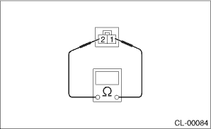
(2) Measure the resistance between terminal 1 and 2 of the switch. If the resistance is not at the standard value, replace the switch.
Condition | Terminal No. | Specified resistance |
ON | No. 1 — No. 2 | Less than 1 ? |
OFF | No. 1 — No. 2 | 1 M? or more |
(3) Check that the switch is turned on and off in dimension L.
Dimension L:
5 — 6.5 mm (0.2 — 0.26 in)
(A) | ON |
(B) | OFF |
(4) Install the clutch switch. Clutch Switch > INSTALLATION">
 Removal
CLUTCH SYSTEM > Clutch SwitchREMOVALCAUTION:Before handling the airbag system components, refer to “CAUTION” of “General Description” in “AIRBAG SYSTEM”. Genera ...
 Installation
CLUTCH SYSTEM > Clutch SwitchINSTALLATION1. CLUTCH SWITCH1. Install the clutch switch.2. Move the clevis pin of push rod to left and right, retain it at the position where it moves smoothly, and me ...
Other materials:
Inspection
WIPER AND WASHER SYSTEMS > Rear Wiper MotorINSPECTIONCAUTION:Fix the motor to prevent the motor from being shorted by moving during operation.1. Connect the battery to the motor assembly - rear wiper connector, and check that the motor assembly - rear wiper operates.2. Connect the battery to term ...
General settings
Touch the tab for the audio unit
basic
settings.
Item
Function
System
Language
Select to change the language
Button
Beeps
Select to set the sound beeps
on/off.
System
Software
Select to update software versions.
This menu is not ...
Installation
MANUAL TRANSMISSION AND DIFFERENTIAL(5MT) > Front Differential AssemblyINSTALLATION1. Install the differential side retainers using ST.ST 18630AA010WRENCH COMPL RETAINER2. Install the taper roller bearing outer race to the transmission case.3. Install the front differential assembly.NOTE:Be ca ...
