Subaru Crosstrek Service Manual: Dtc p0038 a/f / o2 heater control circuit high bank 1 sensor 2
ENGINE (DIAGNOSTICS)(H4DO) > Diagnostic Procedure with Diagnostic Trouble Code (DTC)
DTC P0038 A/F / O2 HEATER CONTROL CIRCUIT HIGH BANK 1 SENSOR 2
DTC DETECTING CONDITION:
Detected when two consecutive driving cycles with fault occur.
CAUTION:
After servicing or replacing faulty parts, perform Clear Memory Mode Clear Memory Mode > OPERATION"> , and Inspection Mode Inspection Mode > PROCEDURE">.
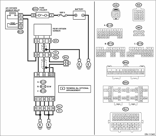
WIRING DIAGRAM:
Engine electrical system Engine Electrical System">
| STEP | CHECK | YES | NO |
1.CHECK HARNESS BETWEEN ECM AND REAR OXYGEN SENSOR CONNECTOR.
1) Turn the ignition switch to OFF.
2) Measure the voltage between ECM connector and chassis ground.
Connector & terminal
(B134) No. 6 (+) — Chassis ground (−):
Is the voltage 10 V or more?
Repair the short circuit to power in the harness between ECM connector and rear oxygen sensor connector.
Diagnostic Procedure with Diagnostic Trouble Code (DTC) > DTC P0038 A/F / O2 HEATER CONTROL CIRCUIT HIGH BANK 1 SENSOR 2">Go to Step 2.
2.CHECK GROUND CIRCUIT FOR ECM.
1) Disconnect the connector from ECM.
2) Measure the resistance between ECM connector and chassis ground.
Connector & terminal
(B134) No. 3 — Chassis ground:
(B134) No. 4 — Chassis ground:
(B136) No. 1 — Chassis ground:
(B136) No. 2 — Chassis ground:
(B136) No. 3 — Chassis ground:
Is the resistance less than 5 ??
Repair the poor contact of ECM connector.
Repair the harness and connector.
NOTE:
In this case, repair the following item:
• Open circuit of harness between ECM connector and engine ground
• Poor contact of coupling connector
1. OUTLINE OF DIAGNOSIS
Detect the rear oxygen sensor heater open or short circuit.
The rear oxygen sensor heater performs duty control, and the output terminal voltage at ON is 0 V, and the output terminal voltage at OFF is the battery voltage.
Judge as NG when the terminal voltage remains High.
2. COMPONENT DESCRIPTION
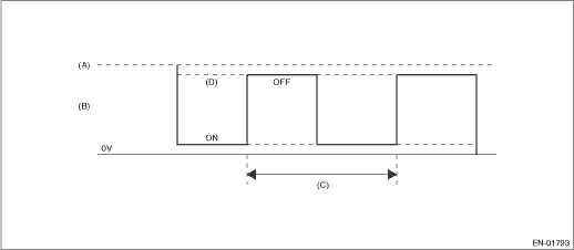
(A) | Battery voltage | (B) | Output voltage of the rear oxygen sensor heater | (C) | 256 ms (cycles) |
(D) | High error |
3. EXECUTION CONDITION
Secondary Parameters | Execution condition |
Battery voltage | ≥ 10.9 V |
Secondary oxygen sensor heater control duty | ≥ 20 % |
4. GENERAL DRIVING CYCLE
After starting the engine, perform the diagnosis continuously when engine is low speed.
5. DIAGNOSTIC METHOD
If the duration of time while the following conditions are met is longer than the time indicated, judge as NG.
Malfunction Criteria | Threshold Value |
Measured secondary oxygen sensor heater control voltage | 12 V battery system voltage ? 0.30 V |
Time Needed for Diagnosis: 2.56 seconds
Malfunction Indicator Light Illumination: Illuminates when malfunction occurs in 2 continuous driving cycles.
 Dtc p0037 a/f / o2 heater control circuit low bank 1 sensor 2
ENGINE (DIAGNOSTICS)(H4DO) > Diagnostic Procedure with Diagnostic Trouble Code (DTC)DTC P0037 A/F / O2 HEATER CONTROL CIRCUIT LOW BANK 1 SENSOR 2DTC DETECTING CONDITION:Detected when two consecutiv ...
 Dtc p0068 map/maf - throttle position correlation
ENGINE (DIAGNOSTICS)(H4DO) > Diagnostic Procedure with Diagnostic Trouble Code (DTC)DTC P0068 MAP/MAF - THROTTLE POSITION CORRELATIONDTC detecting condition:Detected when two consecutive driving cy ...
Other materials:
Vehicle Dynamics Control warning
light
CAUTION
The Vehicle Dynamics Control system
provides its ABS control
through the electrical circuit of the
ABS. Accordingly, if the ABS is
inoperative, the Vehicle Dynamics
Control system becomes unable to
provide ABS control. As a result, the
Vehicle Dynamics Control system
also becomes ...
List of diagnostic trouble code (dtc) List
BODY CONTROL SYSTEM (DIAGNOSTICS) > List of Diagnostic Trouble Code (DTC)LISTDTCItemContent of diagnosisNoteB1010BODY CONTROL SYSTEM (BIU) MALFUNCTIONBody integrated unit internal error Diagnostic Procedure with Diagnostic Trouble Code (DTC) > DTC B1010 BODY CONTROL SYSTEM (BIU) MALFUNCTION&qu ...
Second-row seats
The Subaru Ascent second-row seating system is designed to deliver exceptional
comfort, flexibility, and safety for passengers. Whether equipped with captain seats
or a bench configuration, the Subaru Ascent ensures optimal ergonomics and reliable
restraint performance during every journey ...
