
Subaru Crosstrek Service Manual: Disassembly
MECHANICAL(H4DO) > Cylinder Head
DISASSEMBLY
1. Remove the chain cover securing bolt from the cylinder head LH.
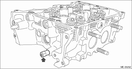
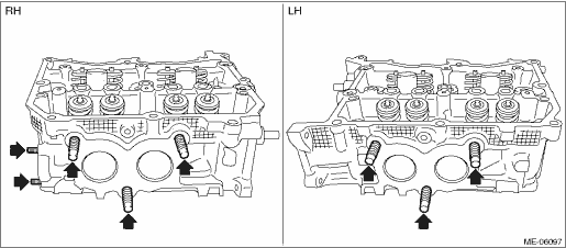
2. Remove the stud bolts from the cylinder head.
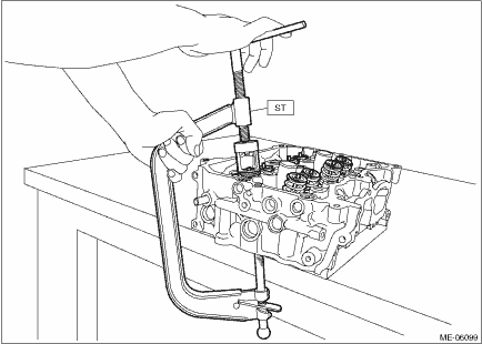
3. Remove the valve collet, valve, valve spring retainer, valve spring and valve spring seat from the cylinder head RH.
CAUTION:
During work, place a waste cloth, etc. to avoid scratching the mating surface of the cylinder head RH.
NOTE:
• Mark each part to prevent confusion.
• Keep all the removed parts in order for re-installing in their original positions.
(1) Compress the valve spring and remove the valve collet using ST.
| ST 0920287002000 | REMOVER AND REPLACER |
(2) Remove valve, valve spring retainer, valve spring and valve spring seat.
4. Remove the valve collet, valve, valve spring retainer, valve spring and valve spring seat from the cylinder head LH.
5. Remove the valve oil seals from valve guides of cylinder head RH.
CAUTION:
• During work, place a waste cloth, etc. to avoid scratching the mating surface of the cylinder head RH.
• Use special care not to damage the cylinder head RH and guide during work.
NOTE:
For removal of valve guide, refer to INSPECTION. Cylinder Head > INSPECTION">
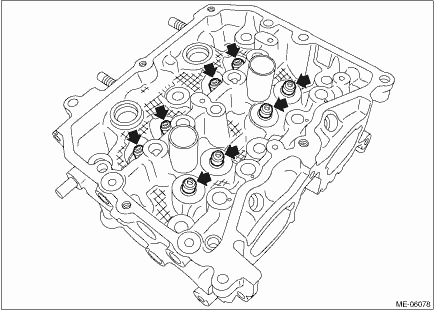
6. For cylinder head LH, remove the valve oil seal in the same manner.
 Removal
MECHANICAL(H4DO) > Cylinder HeadREMOVAL1. CYLINDER HEAD RH1. Remove the engine from the vehicle. Engine Assembly > REMOVAL">2. Remove the intake manifold. Intake Manifold > REMOVAL& ...
 Inspection
MECHANICAL(H4DO) > Cylinder HeadINSPECTION1. CYLINDER HEAD1. Visually inspect to make sure that there are no cracks, scratches or other damage.2. Use liquid penetrant tester on the important sectio ...
Other materials:
Dtc u0151 lost communication with restraints control module
LAN SYSTEM (DIAGNOSTICS) > Diagnostic Procedure with Diagnostic Trouble Code (DTC)DTC U0151 LOST COMMUNICATION WITH RESTRAINTS CONTROL MODULEDTC DETECTING CONDITION:No data is received from airbag CM.TROUBLE SYMPTOM:Cooperation control with airbag CM does not operate properly.STEPCHECKYESNO1.CHEC ...
Removal
LIGHTING SYSTEM > Ignition Switch IlluminationREMOVALNOTE:The ignition switch illumination is integrated into the immobilizer antenna assembly.1. Disconnect the ground cable from battery. NOTE">2. Remove the cover assembly - column.(1) Remove the screws by turning the steering wheel to r ...
Removal
COOLING(H4DO) > Water PumpREMOVAL1. WATER PUMP PULLEY1. Disconnect the ground cable from battery. NOTE">2. Remove the V-belt covers.3. Remove the V-belts. V-belt > REMOVAL">4. Remove the radiator main fan & fan motor assembly. Radiator Main Fan and Fan Motor > REMOVAL ...
