Subaru Crosstrek Service Manual: Removal
MECHANICAL(H4DO) > Cylinder Head
REMOVAL
1. CYLINDER HEAD RH
1. Remove the engine from the vehicle. Engine Assembly > REMOVAL">
2. Remove the intake manifold. Intake Manifold > REMOVAL">
3. Remove the engine wiring harness. Engine Wiring Harness > REMOVAL">
4. Remove the tumble generator valve assembly RH. Tumble Generator Valve Assembly > REMOVAL">
5. Remove the chain cover. Chain Cover > REMOVAL">
6. Remove the rocker cover RH. Rocker Cover > REMOVAL">
7. Remove the cam carrier RH. Cam Carrier > REMOVAL">
8. Remove the EGR cooler. EGR Cooler > REMOVAL">
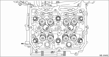
9. Loosen the bolts holding the cylinder head RH equally, a little at a time in numerical sequence as shown in the figure, and while leaving the cylinder head bolts (1) and (4) engaged by three or four threads, remove the other cylinder head bolts.
NOTE:
Leaving the cylinder head bolts (1) and (4) engaged by three or four threads prevents the cylinder head RH from falling.
10. While tapping the cylinder head RH with a plastic hammer, separate it from cylinder block RH.
11. Remove the bolts (1) and (4) to remove cylinder head RH.
12. Remove the cylinder head gasket RH.
CAUTION:
Be careful not to scratch the mating surface of cylinder head and cylinder block.
13. Remove the liquid gasket from cylinder head RH and cam carrier RH.
2. CYLINDER HEAD LH
1. Remove the engine from the vehicle. Engine Assembly > REMOVAL">
2. Remove the intake manifold. Intake Manifold > REMOVAL">
3. Remove the engine wiring harness. Engine Wiring Harness > REMOVAL">
4. Remove the tumble generator valve assembly LH. Tumble Generator Valve Assembly > REMOVAL">
5. Remove the chain cover. Chain Cover > REMOVAL">
6. Remove the rocker cover LH. Rocker Cover > REMOVAL">
7. Remove the cam carrier LH. Cam Carrier > REMOVAL">
8. Remove the A/C compressor. Compressor > REMOVAL">
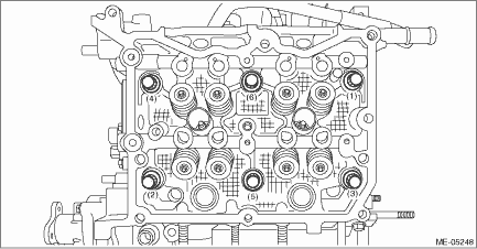
9. Loosen the bolts holding the cylinder head LH equally, a little at a time in numerical sequence as shown in the figure, and while leaving the cylinder head bolts (1) and (4) engaged by three or four threads, remove the other cylinder head bolts.
NOTE:
Leaving the cylinder head bolts (1) and (4) engaged by three or four threads prevents the cylinder head LH from falling.
10. While tapping the cylinder head LH with a plastic hammer, separate it from cylinder block LH.
11. Remove the cylinder head bolts (1) and (4) to remove cylinder head LH.
12. Remove the cylinder head gasket LH.
CAUTION:
Be careful not to scratch the mating surface of cylinder head and cylinder block.
13. Remove the liquid gasket from cylinder head LH and cam carrier LH.
 Assembly
MECHANICAL(H4DO) > Cylinder HeadASSEMBLY(1)Exhaust valve(6)Valve spring(11)Intake valve guide(2)Intake valve(7)Valve spring retainer(12)Exhaust valve guide(3)Cylinder head(8)Valve collet(13)Roller ...
 Disassembly
MECHANICAL(H4DO) > Cylinder HeadDISASSEMBLY1. Remove the chain cover securing bolt from the cylinder head LH.2. Remove the stud bolts from the cylinder head.3. Remove the valve collet, valve, valve ...
Other materials:
Dtc b16f9 door sensor rh recognition error
AIRBAG SYSTEM (DIAGNOSTICS) > Diagnostic Chart with Trouble CodeDTC B16F9 DOOR SENSOR RH RECOGNITION ERRORDiagnosis start condition:Ignition voltage is 10 V to 16 V.DTC detecting condition:• Front door impact sensor (RH) is misinstalled.• Airbag control module is faulty.CAUTION:Before ...
Ending screen
If "Eco Summary" is set to "On" in the
"Bypass screen setting", the "Fuel consumption
results screen" will be displayed
before the screen turns off when the
ignition switch is turned to the "LOCK"/
"OFF" position.
Fuel consumption results screen
The average fuel consumption for the
e ...
Installation
FUEL INJECTION (FUEL SYSTEMS)(H4DO) > Front Oxygen (A/F) SensorINSTALLATIONCAUTION:If lubricant is spilt over the exhaust pipe, wipe it off with cloth to avoid emission of smoke or causing a fire.1. Before installing front oxygen (A/F) sensor, apply anti-seize compound only to the threaded portio ...
