Subaru Crosstrek Service Manual: Installation
CONTINUOUSLY VARIABLE TRANSMISSION(TR580) > Forward Clutch Assembly
INSTALLATION
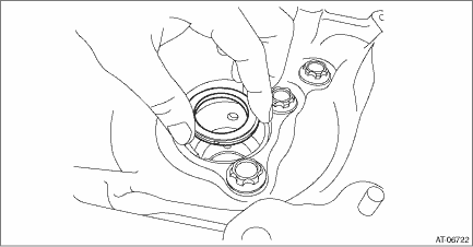
1. Install the thrust bearing to the converter case.
NOTE:
Face the temper color surface to the converter case side.
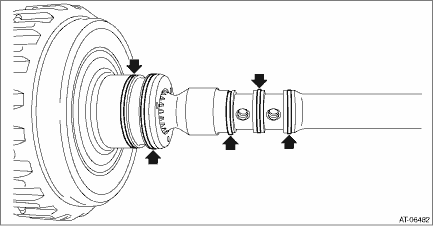
2. Install the seal ring to the input shaft.
NOTE:
• Use new seal rings.
• When installing the seal rings, do not expand the seal rings too much.
• Apply CVTF to the seal rings.
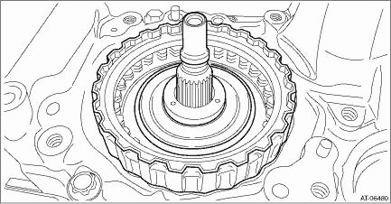
3. Install the forward clutch assembly to the converter case.
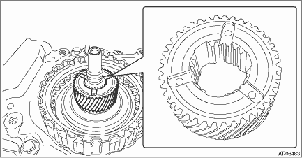
4. Install the sun gear.
NOTE:
Face the end face of the sun gear to the reverse brake side as shown in the figure.
5. Install the thrust bearing to the sun gear.
NOTE:
Face the temper color surface to the reverse brake side.
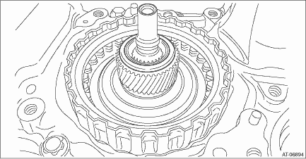
6. Install the planetary carrier.
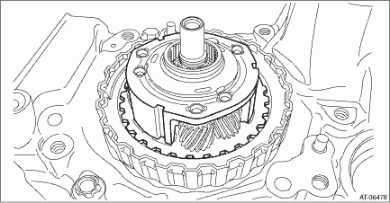
7. Install the thrust bearing.
NOTE:
Face the temper color surface to the reverse brake side.
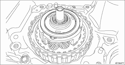
8. Install the internal gear.
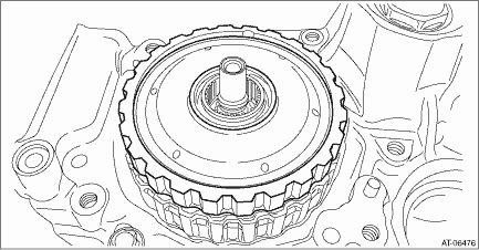
9. Install the thrust bearing to the internal gear.
NOTE:
Face the temper color surface to the reverse brake side.
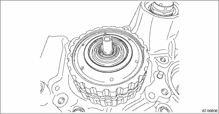
10. Select a washer. Forward Clutch Assembly > ADJUSTMENT">
11. Install the reverse brake assembly. Reverse Brake Assembly > INSTALLATION">
12. Install the primary pulley, secondary pulley and variator chain. Primary Pulley and Secondary Pulley > INSTALLATION">
13. Install the reduction drive gear. Reduction Drive Gear > INSTALLATION">
14. Install the transmission case. Transmission Case > INSTALLATION">
15. Install the transmission control device. Transmission Control Device > INSTALLATION">
16. Install the oil strainer and oil pan. Oil Pan and Strainer > INSTALLATION">
17. Install the reduction driven gear assembly. Reduction Driven Gear > INSTALLATION">
18. Install the transfer driven gear assembly. Transfer Driven Gear > INSTALLATION">
19. Install the transfer clutch assembly. Transfer Clutch > INSTALLATION">
20. Install the parking pawl. Parking Pawl > INSTALLATION">
21. Install the extension case. Extension Case > INSTALLATION">
22. Install the inhibitor switch. Inhibitor Switch > INSTALLATION">
23. Install the secondary speed sensor. Secondary Speed Sensor > INSTALLATION">
24. Install the primary speed sensor. Primary Speed Sensor > INSTALLATION">
25. Install the turbine speed sensor. Turbine Speed Sensor > INSTALLATION">
26. Install the transmission harness. Transmission Harness > INSTALLATION">
27. Install the control valve body. Control Valve Body > INSTALLATION">
28. Install the air breather hose. Air Breather Hose > INSTALLATION">
29. Install the transmission assembly to the vehicle. Automatic Transmission Assembly > INSTALLATION">
 Inspection
CONTINUOUSLY VARIABLE TRANSMISSION(TR580) > Forward Clutch AssemblyINSPECTION• Check the forward clutch drum, internal gear, sun gear and forward clutch piston lip for wear or damage.• ...
Other materials:
Removal
MECHANICAL(H4DO) > V-beltREMOVALNOTE:When replacing a single part, perform the work with the engine assembly installed to body.1. V-BELT1. When working on the vehicleNOTE:When working on the vehicle, perform the following steps also.(1) Remove the V-belt covers.(2) Remove the air intake duct. Ai ...
Shift lock release
If the select lever cannot be operated, turn
the ignition switch back to the "ON"
position then move the select lever to the
"P" position with the select lever button
pressed and brake pedal depressed.
If the select lever does not move after
performing the above procedure, perform
the follo ...
Removal
LIGHTING SYSTEM > Front Fog Light AssemblyREMOVAL1. Disconnect the ground cable from battery. NOTE">2. Lift up the vehicle.3. Remove the screw and clips, and turn over the front side of the mud guard - front.4. From the bottom of the bumper face - front, remove the fog light assembly - f ...

