Subaru Crosstrek Service Manual: Assembly
MECHANICAL(H4DO) > Cylinder Head
ASSEMBLY
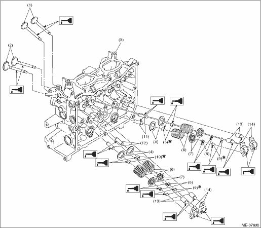
(1) | Exhaust valve | (6) | Valve spring | (11) | Intake valve guide |
(2) | Intake valve | (7) | Valve spring retainer | (12) | Exhaust valve guide |
(3) | Cylinder head | (8) | Valve collet | (13) | Roller rocker arm pivot |
(4) | Valve spring seat | (9) | Valve shim | (14) | Roller rocker arm |
(5) | Intake valve oil seal | (10) | Exhaust valve oil seal |
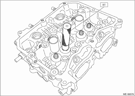
1. Using the ST, install the valve oil seals to valve guides of cylinder head RH.
CAUTION:
• During work, place a waste cloth, etc. to avoid scratching the mating surface of the cylinder head RH.
• Use special care not to damage the cylinder head RH and guide during work.
• When installing the valve oil seal, press the ST with hands to install it and never drive the ST with a plastic hammer, otherwise the valve oil seal can be damaged.
NOTE:
• Use a new valve oil seal.
• Apply engine oil to valve oil seal before installing.
• The intake valve oil seals and exhaust valve oil seals are distinguished by their colors.
Identification colors:
Intake [Gray]
Exhaust [Green]
• For installation of valve guide, refer to INSPECTION. Cylinder Head > INSPECTION">
| ST 18261AA010 | VALVE OIL SEAL GUIDE |
2. For cylinder head LH, install the valve oil seal in the same manner.
3. Install the valve spring seat, valve spring, valve spring retainer, valve and valve collet to the cylinder head RH.
CAUTION:
During work, place a waste cloth, etc. to avoid scratching the mating surface of the cylinder head RH.
(1) Set the valve spring seat, valve spring and valve spring retainer onto the cylinder head RH.
NOTE:
Be sure to install the valve spring with its close-coiled end facing the cylinder head side.
(2) Coat the valve stem of each valve with engine oil and insert the valve into valve guide.
NOTE:
When inserting the valve into valve guide, use special care not to damage the oil seal lip.
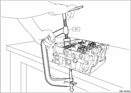
(3) Compress the valve spring and install the valve collet using ST.
| ST 0920287002000 | REMOVER AND REPLACER |
4. Install the valve spring seat, valve spring, valve spring retainer, valve and valve collet to the cylinder head LH.
5. Lightly tap the valve spring retainer with a plastic hammer, and make sure that the valve collet is securely attached.
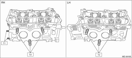
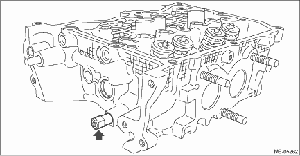
6. Install the stud bolts onto cylinder heads.
Tightening torque:
T1: 6.4 N·m (0.7 kgf-m, 4.7 ft-lb)
T2: 18 N·m (1.8 kgf-m, 13.3 ft-lb)
7. Install the chain cover securing bolt to the cylinder head LH.
Tightening torque:
6.4 N·m (0.7 kgf-m, 4.7 ft-lb)
 Cylinder head
...
 Removal
MECHANICAL(H4DO) > Cylinder HeadREMOVAL1. CYLINDER HEAD RH1. Remove the engine from the vehicle. Engine Assembly > REMOVAL">2. Remove the intake manifold. Intake Manifold > REMOVAL& ...
Other materials:
Switching power status
1. Apply the parking brake.
2. Shift the select lever into the "P"
position.
3. Depress the brake pedal.
4. Hold the access key with the buttons
facing you, and touch the push-button
ignition switch with it.
When the communication between the
access key and the vehicle is completed ...
Inspection
CONTROL SYSTEMS > MT Gear Shift LeverINSPECTION1. Check the parts (bushing, cushion rubber, spacer, boot, stay and rod, etc.) for deformation, damage and wear. If necessary, correct or replace faulty parts. Compare the removed parts with new parts to judge if there are damages or not.(A)Bushing(B ...
Ornament Installation
EXTERIOR/INTERIOR TRIM > OrnamentINSTALLATION1. LETTER MARKAlign the end of application tape with the end of panel, then adhere the letter mark.(a)Panel - rear gate end(b)Application tape end NOTE:• Align the cutout of application tape with the end reference of the front door. (a)• A ...
