Subaru Crosstrek Service Manual: Installation
FUEL INJECTION (FUEL SYSTEMS)(H4DO) > Fuel Filler Pipe
INSTALLATION
1. Open the fuel filler lid.
2. Insert the fuel filler pipe assembly into the rubber saucer from inside of the rear fender.
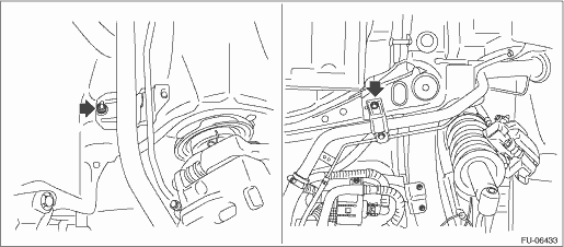
3. Install the fuel filler pipe assembly to the vehicle.
Tightening torque:
7.5 N·m (0.8 kgf-m, 5.5 ft-lb)
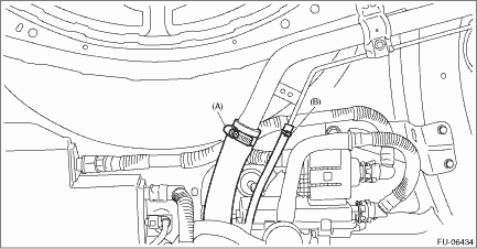
4. Securely insert the fuel filler hose (A) and evaporation hose (B) until the hose end contacts the spool, then attach the clamp or clip as shown in the figure.
Tightening torque:
2.5 N·m (0.3 kgf-m, 1.8 ft-lb)
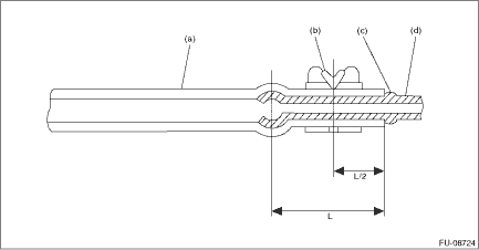
(a) | Hose | (c) | Spool or bump | (d) | Pipe |
(b) | Clamp or clip |
5. Install the rear mud guard RH. Mud Guard > INSTALLATION">
6. Install the rear sub frame assembly. Rear Sub Frame > INSTALLATION">
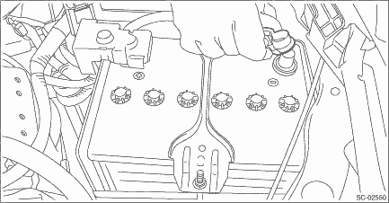
7. Connect the battery ground terminal.
8. Inspect the wheel alignment and adjust if necessary.
9. Perform reinitialization of the auto headlight beam leveler system. (Model with auto headlight beam leveler) Auto Headlight Beam Leveler System > PROCEDURE">
10. Adjust the steering angle sensor. VDC Control Module and Hydraulic Control Unit (VDCCM&H/U) > ADJUSTMENT">
 Removal
FUEL INJECTION (FUEL SYSTEMS)(H4DO) > Fuel Filler PipeREMOVALWARNING:Place “NO OPEN FLAMES” signs near the working area.CAUTION:Be careful not to spill fuel.1. Release the fuel pressure ...
 Fuel filter
...
Other materials:
Caution
LAN SYSTEM (DIAGNOSTICS) > General DescriptionCAUTION1. SUPPLEMENTAL RESTRAINT SYSTEM “AIRBAG”Airbag system wiring harness is routed near the body integrated unit and twisted pair line.CAUTION:• Do not use the electrical test equipment on all airbag system wiring harnesses and c ...
Continuously variable transmission features
The continuously variable transmission is
electronically controlled and provides an
infinite number of forward speeds and 1
reverse speed. It also has a manual mode.
NOTE
When the engine coolant temperature
is still low, the transmission will
upshift or downshift at higher engine
speed ...
Removal
CLUTCH SYSTEM > Master CylinderREMOVALCAUTION:• Be careful not to spill the brake fluid. Brake fluid spilled on the vehicle body will harm the paint surface; wash it off with water and wipe clean quickly if spilled.• Before handling the airbag system components, refer to “CAUTIO ...
