Subaru Crosstrek Service Manual: Installation
CLUTCH SYSTEM > Clutch Switch
INSTALLATION
1. CLUTCH SWITCH
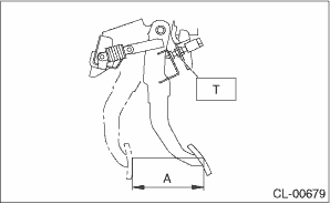
1. Install the clutch switch.
2. Move the clevis pin of push rod to left and right, retain it at the position where it moves smoothly, and measure the clutch pedal stroke.
Clutch pedal full stroke A:
130 — 135 mm (5.12 — 5.31 in)
Tightening torque:
T: 8 N·m (0.8 kgf-m, 5.9 ft-lb)
3. If the clutch pedal stroke is out of specification, adjust the stroke. Clutch Pedal > ADJUSTMENT">
4. Connect the clutch switch connector.
5. Thereafter, install in the reverse order of removal.
Tightening torque:
Knee airbag module
7.5 N·m (0.76 kgf-m, 5.5 ft-lb)
2. CLUTCH START SWITCH
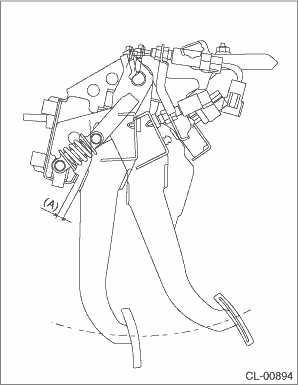
1. Remove the snap pin and clevis pin connecting the clutch pedal and operating rod.

(A) | Clevis pin |
(B) | Snap pin |
(C) | Push rod |
(D) | Lock nut |
2. Install the clutch start switch so that the clutch switch turns on when the clearance between clutch pedal stopper and clutch pedal is within the specification described below.
Clearance A:
6.3 — 8.6 mm (0.25 — 0.34 in)
Tightening torque:
8 N·m (0.8 kgf-m, 5.9 ft-lb)
NOTE:
• Using a plate of the same thickness for the clearance facilitates the adjustment operation.
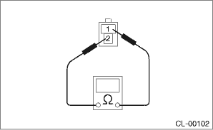
• Using the Subaru Select Monitor or a tester, check the position where the switch turns on.
Check the following figure for the terminal layout of the harness connector.
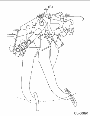
• When performing adjustment by the clearance between clutch start switch and clutch pedal plate, perform installation according to the following gap.
Clearance B:
8.6 — 9.0 mm (0.34 — 0.35 in)
3. Connect the clutch start switch connector.
4. Make sure that engine does not start with clutch pedal not depressed.
5. Make sure that engine starts with clutch pedal depressed.
6. Thereafter, install in the reverse order of removal.
Tightening torque:
Knee airbag module
7.5 N·m (0.76 kgf-m, 5.5 ft-lb)
 Inspection
CLUTCH SYSTEM > Clutch SwitchINSPECTION1. CLUTCH START SWITCH1. Perform the following inspections. If the clutch start switch does not operate normally, adjust the switch, and check it again. Clut ...
 Flywheel
...
Other materials:
Cruise control (if equipped)
NOTE
For models with EyeSight system:
Refer to the Owner's Manual supplement
for the EyeSight system.
Cruise control enables you to maintain a
constant vehicle speed without holding
your foot on the accelerator pedal and it is
operative when the vehicle speed is 25
mph (40 km/h) or more.
WA ...
Dtc p2138 throttle/pedal position sensor/switch "d"/"e" voltage correlation
ENGINE (DIAGNOSTICS)(H4DO) > Diagnostic Procedure with Diagnostic Trouble Code (DTC)DTC P2138 THROTTLE/PEDAL POSITION SENSOR/SWITCH "D"/"E" VOLTAGE CORRELATIONDTC DETECTING CONDITION:Immediately at fault recognitionTROUBLE SYMPTOM:• Improper idling• Poor driving pe ...
Removal
BRAKE > Rear Brake PadREMOVAL1. Lift up the vehicle, and then remove the rear wheels.2. Remove the rear brake pad.(1) Remove the bolts and remove the brake hose bracket.(2) Remove the caliper bolt, and raise and hold the caliper body assembly.NOTE:Do not disconnect the brake hose from the caliper ...
