Subaru Crosstrek Service Manual: Installation
EXTERIOR BODY PANELS > Front Door
INSTALLATION
1. FRONT DOOR PANEL
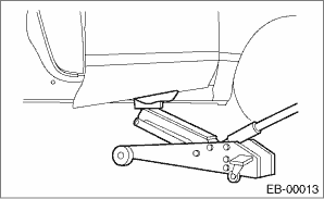
1. Put a wooden block on a jack and place the panel assembly - front door on it.
2. Apply grease to the sliding area of door hinges, and install the door hinge to vehicle.
3. Adjust the height by the jack, and temporarily install the panel assembly - front door to the upper hinge - front door and the lower hinge - front door.
NOTE:
• When installing the panel assembly - front door, make sure that a uniform clearance is created around the panel.
• Perform installation while paying attention to the assembly direction of the grommet.
4. Adjust the clearance around the panel assembly - front door. Front Door > ADJUSTMENT">
5. Tighten the bolts and nuts of the door hinge and the checker assembly - front door.
Tightening torque:
Refer to “COMPONENT” of “General Description”. General Description > COMPONENT">
6. Install door internal parts in the reverse order of removal.
NOTE:
Before installation, check the following items.
• Rod of the latch and actuator assembly - front is free from deformation.
• Grease is applied sufficiently to the rod joints of the latch and actuator assembly - front.
• Cable of the latch and actuator assembly - front is free from deformation such as fray.
• Grease is applied sufficiently to the cable joints of the latch and actuator assembly - front.
7. Connect door harness connector, and install the cover side sill - front.
2. FRONT DOOR HINGE
1. Apply grease to the sliding area of door hinges, and install the door hinge to vehicle.
2. Adjust the height by the jack, and temporarily install the panel assembly - front door to the upper hinge - front door and the lower hinge - front door.
NOTE:
When installing the panel assembly - front door, make sure that a uniform clearance is created around the panel.
3. Adjust the clearance around the panel assembly - front door. Front Door > ADJUSTMENT">
4. Tighten the bolts and nuts of the door hinge and the checker assembly - front door.
Tightening torque:
Refer to “COMPONENT” of “General Description”. General Description > COMPONENT">
 Removal
EXTERIOR BODY PANELS > Front DoorREMOVAL1. FRONT DOOR PANEL1. Disconnect the ground cable from battery and wait for at least 60 seconds before starting work. NOTE">2. Remove the trim panel ...
 Front fender
...
Other materials:
Removal
FUEL INJECTION (FUEL SYSTEMS)(H4DO) > Engine Coolant Temperature SensorREMOVAL1. Disconnect the ground cable from battery.2. Drain engine coolant. Engine Coolant > REPLACEMENT">3. Disconnect the connector (A) from the engine coolant temperature sensor, and remove the engine coolant te ...
Disassembly
POWER ASSISTED SYSTEM (POWER STEERING) > Electric Power Steering GearboxDISASSEMBLYCAUTION:• Nut for fixing the rack is on the driver’s side only. When removing the tie-rod on the passenger’s side, turn over the boot - steering gearbox on the driver’s side, and fix the rac ...
Dtc p1160 throttle return spring
ENGINE (DIAGNOSTICS)(H4DO) > Diagnostic Procedure with Diagnostic Trouble Code (DTC)DTC P1160 THROTTLE RETURN SPRINGNOTE:For the diagnostic procedure, refer to DTC P2101. Diagnostic Procedure with Diagnostic Trouble Code (DTC) > DTC P2101 THROTTLE ACTUATOR "A" CONTROL MOTOR CIRCUIT ...
