Subaru Crosstrek Service Manual: Dtc b2a0d airbag signal
TELEMATICS SYSTEM (DIAGNOSTICS) > Diagnostic Procedure with Diagnostic Trouble Code (DTC)
DTC B2A0D AIRBAG SIGNAL
Diagnosis start condition:
When ignition switch is ON.
DTC detecting condition:
Either the regular signal or collision signal cannot be detected from the airbag CM for at least 30 seconds.
Trouble symptom:
• ACN function does not operate.
• RED LED illuminates.
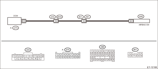
Wiring diagram:
NOTE:
For the coupling connector, refer to “WIRING SYSTEM”.
Telematics Telematics System > WIRING DIAGRAM">
CAUTION:
• CommCheck is required after replacing the DCM. Telematics System > OPERATION">
• Before performing diagnosis, refer to “CAUTION” in “General Description” in Airbag System. General Description > CAUTION">
| STEP | CHECK | YES | NO |
1.CHECK DTC.
Read the DTC. Diagnostic Code(s) Display">
Is DTC B2A0D displayed? (Current malfunction)
Diagnostic Procedure with Diagnostic Trouble Code (DTC) > DTC B2A0D AIRBAG SIGNAL">Go to Step 2.
Even if DTC is displayed, the circuit has returned to a normal condition at this time. Reproduce the failure, and then perform the diagnosis again.
In this case, temporary poor contact of connector, temporary open or short circuit of harness may be the cause.
2.CHECK DTC.
Read DTC of the airbag. Read Diagnostic Trouble Code (DTC)">
Is DTC displayed? (Current malfunction)
Perform the diagnosis according to DTC.
Diagnostic Procedure with Diagnostic Trouble Code (DTC) > DTC B2A0D AIRBAG SIGNAL">Go to Step 3.
3.CHECK HARNESS (OPEN CIRCUIT).
1) Turn the ignition switch to OFF, disconnect the battery ground cable, and wait for 60 seconds or more.
2) Disconnect the airbag CM connector.
3) Disconnect the DCM connector.
4) Measure the resistance between airbag CM connector and DCM connector.
CAUTION:
To measure the voltage and resistance of airbag system component, be sure to use the specified test harness. General Description">
Connector & terminal
(i270) No. 18 — (AB6) No. 24:
Is the resistance 1 ? or less?
Diagnostic Procedure with Diagnostic Trouble Code (DTC) > DTC B2A0D AIRBAG SIGNAL">Go to Step 4.
Repair or replace the open circuit of harness.
4.CHECK HARNESS (GROUND SHORT CIRCUIT).
Measure the resistance between DCM connector and chassis ground.
Connector & terminal
(i270) No. 18 — Chassis ground:
Is the resistance 1 M? or more?
Diagnostic Procedure with Diagnostic Trouble Code (DTC) > DTC B2A0D AIRBAG SIGNAL">Go to Step 5.
Repair or replace the short circuit of the harness.
5.CHECK THE CONNECTOR (SHORT CIRCUIT TO POWER SUPPLY).
Measure the voltage between DCM connector and chassis ground.
Connector & terminal
(i270) No. 18 (+) — Chassis ground (−):
Is the voltage less than 1 V?
Replace the DCM. Data Communication Module">
Repair or replace the short circuit of the harness.
 Dtc b2a0c dcm internal fault
TELEMATICS SYSTEM (DIAGNOSTICS) > Diagnostic Procedure with Diagnostic Trouble Code (DTC)DTC B2A0C DCM INTERNAL FAULTDIAGNOSIS START CONDITION:When ignition switch is ON.DTC DETECTING CONDITION:&bu ...
 Dtc b2a0e mute line circuit
TELEMATICS SYSTEM (DIAGNOSTICS) > Diagnostic Procedure with Diagnostic Trouble Code (DTC)DTC B2A0E MUTE LINE CIRCUITDiagnosis start condition:When ignition switch is ON.DTC detecting condition:Any ...
Other materials:
Dtc u0101 lost communication with tcm
KEYLESS ACCESS WITH PUSH BUTTON START SYSTEM (DIAGNOSTICS) > Diagnostic Procedure with Diagnostic Trouble Code (DTC)DTC U0101 LOST COMMUNICATION WITH TCMDetected when CAN data from TCM does not arrive.NOTE:Perform the diagnosis for LAN system. Basic Diagnostic Procedure > PROCEDURE"> ...
If your vehicle is involved in an accident
CAUTION
If your vehicle is involved in an
accident, be sure to inspect the
ground under the vehicle before
restarting the engine. If you find that
fuel has leaked on the ground, do
not try to restart the engine. The fuel
system has been damaged and is in
need of repair. Immediately contact
...
Hill start assist warning light does not go off
VEHICLE DYNAMICS CONTROL (VDC) (DIAGNOSTICS) > Warning Light Illumination PatternHILL START ASSIST WARNING LIGHT DOES NOT GO OFFDetecting condition:• Defective combination meter• Defective CAN communicationTrouble symptom:Hill start assist warning light does not go off when starting t ...
