Subaru Crosstrek Service Manual: Dtc b2a0e mute line circuit
TELEMATICS SYSTEM (DIAGNOSTICS) > Diagnostic Procedure with Diagnostic Trouble Code (DTC)
DTC B2A0E MUTE LINE CIRCUIT
Diagnosis start condition:
When ignition switch is ON.
DTC detecting condition:
Any of the following conditions occurs continuously for five seconds or more after the ignition switch is turned to ON when DCM does not mute the audio or navigation system.
• Current in the mute line is less than 1 mA. (Improper line connection, etc.)
• Current exceeds 50 mA. (Short-circuited line, etc.)
Trouble symptom:
• The mute function of audio or navigation system does not operate.
• RED LED illuminates.
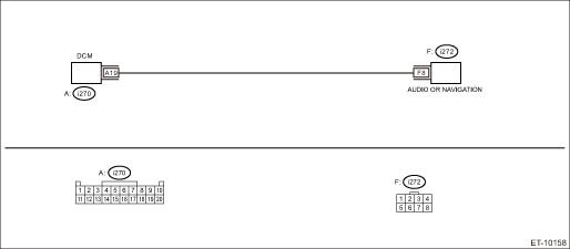
Wiring diagram:
Telematics Telematics System > WIRING DIAGRAM">
CAUTION:
CommCheck is required after replacing the DCM. Telematics System > OPERATION">
| STEP | CHECK | YES | NO |
1.CHECK DTC.
Read the DTC. Diagnostic Code(s) Display">
Is DTC B2A0E displayed? (Current malfunction)
Diagnostic Procedure with Diagnostic Trouble Code (DTC) > DTC B2A0E MUTE LINE CIRCUIT">Go to Step 2.
Even if DTC is displayed, the circuit has returned to a normal condition at this time. Reproduce the failure, and then perform the diagnosis again.
In this case, temporary poor contact of connector, temporary open or short circuit of harness may be the cause.
2.CHECK HARNESS (OPEN CIRCUIT).
1) Turn the ignition switch to OFF.
2) Disconnect the audio or navigation connector.
3) Disconnect the DCM connector.
4) Measure the resistance between audio or navigation connector and DCM connector.
Connector & terminal
(i270) No. 19 — (i272) No. 8:
Is the resistance 1 ? or less?
Diagnostic Procedure with Diagnostic Trouble Code (DTC) > DTC B2A0E MUTE LINE CIRCUIT">Go to Step 3.
Repair or replace the open circuit of harness.
3.CHECK HARNESS (GROUND SHORT CIRCUIT).
Measure the resistance between DCM connector and chassis ground.
Connector & terminal
(i270) No. 19 — Chassis ground:
Is the resistance 1 M? or more?
Diagnostic Procedure with Diagnostic Trouble Code (DTC) > DTC B2A0E MUTE LINE CIRCUIT">Go to Step 4.
Repair or replace the short circuit of the harness.
4.CHECK THE CONNECTOR (SHORT CIRCUIT TO POWER SUPPLY).
Measure the voltage between DCM connector and chassis ground.
Connector & terminal
(i270) No. 19 (+) — Chassis ground (−):
Is the voltage less than 1 V?
Replace the DCM. Data Communication Module">
Repair or replace the short circuit of the harness.
 Dtc b2a0d airbag signal
TELEMATICS SYSTEM (DIAGNOSTICS) > Diagnostic Procedure with Diagnostic Trouble Code (DTC)DTC B2A0D AIRBAG SIGNALDiagnosis start condition:When ignition switch is ON.DTC detecting condition:Either t ...
 Dtc b2a0f backup battery degradation
TELEMATICS SYSTEM (DIAGNOSTICS) > Diagnostic Procedure with Diagnostic Trouble Code (DTC)DTC B2A0F BACKUP BATTERY DEGRADATIONDIAGNOSIS START CONDITION:When ignition switch is ON.DTC DETECTING CONDI ...
Other materials:
Installation
CONTINUOUSLY VARIABLE TRANSMISSION(TR580) > Primary Speed SensorINSTALLATIONCAUTION:Be sure to prevent water or oil from contacting the connector terminal of primary speed sensor. If adhesion occurs, replace with a new part.Install in the reverse order of removal.NOTE:• Use new O-rings.&bul ...
Inspection
CLUTCH SYSTEM > Clutch SwitchINSPECTION1. CLUTCH START SWITCH1. Perform the following inspections. If the clutch start switch does not operate normally, adjust the switch, and check it again. Clutch Switch > ADJUSTMENT">• Make sure that engine does not start with clutch pedal no ...
Removal
FUEL INJECTION (FUEL SYSTEMS)(H4DO) > Crankshaft Position SensorREMOVAL1. Disconnect the ground cable from battery.2. Remove the clip (A), and loosen the clamps (B) and (C) securing the air intake boot.3. Remove the air intake boot from the air cleaner case (rear) and throttle body, and move the ...
