Subaru Crosstrek Service Manual: Dtc b2275 engine start request control circuit
KEYLESS ACCESS WITH PUSH BUTTON START SYSTEM (DIAGNOSTICS) > Diagnostic Procedure with Diagnostic Trouble Code (DTC)
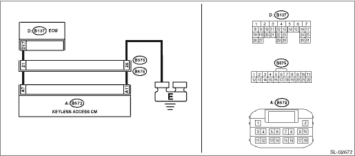
DTC B2275 ENGINE START REQUEST CONTROL CIRCUIT
DTC detecting condition:
• When malfunction is detected in engine start permission signal output circuit in the keyless access CM.
• When malfunction is detected in external engine start permission signal circuit.
Trouble symptom:
Engine will not start.
CAUTION:
For replacement procedure of keyless access CM, refer to the “REGISTRATION MANUAL FOR IMMOBILIZER” provided as a separate volume.
Wiring diagram:
Push button start system Push Button Start System > WIRING DIAGRAM">
| STEP | CHECK | YES | NO |
1.CHECK LAN SYSTEM.
Inspect LAN system. Basic Diagnostic Procedure > PROCEDURE">
Is LAN system normal?
Diagnostic Procedure with Diagnostic Trouble Code (DTC) > DTC B2275 ENGINE START REQUEST CONTROL CIRCUIT">Go to Step 2.
Perform the inspection according to the diagnosis for LAN system.
2.CHECK FUSE.
Check the fuse. Relay and Fuse">
Is the fuse OK?
Diagnostic Procedure with Diagnostic Trouble Code (DTC) > DTC B2275 ENGINE START REQUEST CONTROL CIRCUIT">Go to Step 3.
Replace the fuse. When the replaced fuse is blown immediately, check the power supply circuit for short-circuited.
3.CHECK HARNESS.
1) Disconnect the keyless access CM connector and ECM connector.
2) Using a tester, measure the resistance between the keyless access CM connector and ECM.
Connector & terminal
(B572) No. 7 — (B137) No. 17:
Is the resistance less than 1 ??
Diagnostic Procedure with Diagnostic Trouble Code (DTC) > DTC B2275 ENGINE START REQUEST CONTROL CIRCUIT">Go to Step 4.
Repair or replace the open circuit of harness.
4.CHECK HARNESS.
Using a tester, measure the resistance between the keyless access CM connector and chassis ground.
Connector & terminal
(B572) No. 11 — Chassis ground:
Is the resistance less than 1 ??
Diagnostic Procedure with Diagnostic Trouble Code (DTC) > DTC B2275 ENGINE START REQUEST CONTROL CIRCUIT">Go to Step 5.
Repair or replace the open circuit of harness.
5.CHECK HARNESS.
Using a tester, measure the resistance between the keyless access CM connector and chassis ground.
Connector & terminal
(B572) No. 7 — Chassis ground:
Is the resistance 10 k? or more?
Diagnostic Procedure with Diagnostic Trouble Code (DTC) > DTC B2275 ENGINE START REQUEST CONTROL CIRCUIT">Go to Step 6.
Repair or replace the short circuit of the harness.
6.CHECK KEYLESS ACCESS CM.
1) Connect the keyless access CM connector and ECM connector.
2) Using a tester, measure the voltage between the terminals of keyless access CM connector.
Connector & terminal
(B572) No. 7 (+) — (B572) No. 11 (−):
Is the voltage 2 V or less > 9 V or more when the push button ignition switch is turned on while depressing the brake pedal with the shift position in P or N?
Perform inspection according to the diagnosis of engine. Basic Diagnostic Procedure > PROCEDURE">
Replace the keyless access CM. Keyless Access CM">
 Dtc b2274 acc relay control circuit
KEYLESS ACCESS WITH PUSH BUTTON START SYSTEM (DIAGNOSTICS) > Diagnostic Procedure with Diagnostic Trouble Code (DTC)DTC B2274 ACC RELAY CONTROL CIRCUITDTC detecting condition:When malfunction is de ...
 Dtc b2276 acc relay off signal
KEYLESS ACCESS WITH PUSH BUTTON START SYSTEM (DIAGNOSTICS) > Diagnostic Procedure with Diagnostic Trouble Code (DTC)DTC B2276 ACC RELAY OFF SIGNALDTC detecting condition:When input error occurs in ...
Other materials:
Selection screen
When the
button is pushed and held, the setting screen for each menu can be displayed.
Select the preferred menu by operating
the "
" or "
" switch.
Top menu
Menu option
Description
Time/Date
Time/Date
Set and adjust the time and date. 12h or 24h f ...
Removal
BRAKE > Brake PedalREMOVAL1. CVT MODELCAUTION:Before handling the airbag system components, always refer to “CAUTION” of “General Description” in “AIRBAG SYSTEM”. General Description > CAUTION">1. Disconnect the ground cable from battery and wait fo ...
Replacement
SECURITY AND LOCKS > Access KeyREPLACEMENT1. ACCESS KEY REGISTRATIONNOTE:• A maximum of seven access keys can be registered for each individual vehicle.• When replacing or adding an access key, new registration of the access key is necessary.• When the access key has been newly ...
