Subaru Crosstrek Service Manual: Dtc b2274 acc relay control circuit
KEYLESS ACCESS WITH PUSH BUTTON START SYSTEM (DIAGNOSTICS) > Diagnostic Procedure with Diagnostic Trouble Code (DTC)
DTC B2274 ACC RELAY CONTROL CIRCUIT
DTC detecting condition:
When malfunction is detected in ACC relay drive circuit in the keyless access CM or external circuit.
Trouble symptom:
Each function does not operate at the ACC position.
CAUTION:
For replacement procedure of keyless access CM, refer to the “REGISTRATION MANUAL FOR IMMOBILIZER” provided as a separate volume.
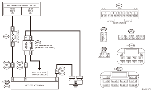
Wiring diagram:
Push button start system Push Button Start System > WIRING DIAGRAM">
| STEP | CHECK | YES | NO |
1.CHECK LAN SYSTEM.
Inspect LAN system. Basic Diagnostic Procedure > PROCEDURE">
Is LAN system normal?
Diagnostic Procedure with Diagnostic Trouble Code (DTC) > DTC B2274 ACC RELAY CONTROL CIRCUIT">Go to Step 2.
Perform the inspection according to the diagnosis for LAN system.
2.CHECK FUSE.
Check the fuse. Relay and Fuse">
Is the fuse OK?
Diagnostic Procedure with Diagnostic Trouble Code (DTC) > DTC B2274 ACC RELAY CONTROL CIRCUIT">Go to Step 3.
Replace the fuse. When the replaced fuse is blown immediately, check the power supply circuit for short-circuited.
3.CHECK HARNESS.
1) Disconnect the keyless access CM connector.
2) Using a tester, measure the voltage between the keyless access CM connector and chassis ground.
Connector & terminal
(B572) No. 2 (+) — Chassis ground (−):
Is the voltage 9.5 — 16 V?
Diagnostic Procedure with Diagnostic Trouble Code (DTC) > DTC B2274 ACC RELAY CONTROL CIRCUIT">Go to Step 4.
Check the power supply circuit.
4.CHECK HARNESS.
Using a tester, measure the resistance between the keyless access CM connector and chassis ground.
Connector & terminal
(B572) No. 11 — Chassis ground:
Is the resistance less than 1 ??
Diagnostic Procedure with Diagnostic Trouble Code (DTC) > DTC B2274 ACC RELAY CONTROL CIRCUIT">Go to Step 5.
Repair or replace the open circuit of harness.
5.CHECK HARNESS.
1) Disconnect the keyless access CM connector.
2) Using a tester, measure the resistance between the keyless access CM connector and chassis ground.
Connector & terminal
(B574) No. 4 — Chassis ground:
Is resistance 152.61 — 216.5 ?? (20°C)
Diagnostic Procedure with Diagnostic Trouble Code (DTC) > DTC B2274 ACC RELAY CONTROL CIRCUIT">Go to Step 7.
Diagnostic Procedure with Diagnostic Trouble Code (DTC) > DTC B2274 ACC RELAY CONTROL CIRCUIT">Go to Step 6.
6.CHECK RELAY.
Perform inspection of ACC relay unit. Accessory Relay (Push Button Start)">
Is the relay OK?
Diagnostic Procedure with Diagnostic Trouble Code (DTC) > DTC B2274 ACC RELAY CONTROL CIRCUIT">Go to Step 7.
Replace the relay.
7.CHECK HARNESS.
Using a tester, measure the resistance between the keyless access CM connector and the accessory relay (push button start), and between the accessory relay (push button start) and chassis ground.
Connector & terminal
(B574) No. 4 — (B426) No. 1:
(B426) No. 2 — Chassis ground:
Is the resistance less than 1 ??
Diagnostic Procedure with Diagnostic Trouble Code (DTC) > DTC B2274 ACC RELAY CONTROL CIRCUIT">Go to Step 8.
Repair or replace the open circuit of harness.
8.CHECK KEYLESS ACCESS CM.
1) Connect the keyless access CM connector.
2) Using a tester, measure the voltage between the keyless access CM connector and chassis ground.
Connector & terminal
(B574) No. 4 (+) — Chassis ground (−):
Is the voltage 1 V or less > 9.5 — 16 V when OFF > ACC ON?
Even if DTC is displayed, the circuit has returned to a normal condition at this time. Reproduce the failure, and then perform the diagnosis again.
NOTE:
In this case, temporary poor contact of connector, temporary open or short circuit of harness may be the cause.
Replace the keyless access CM. Keyless Access CM">
 Dtc b2271 ign relay control circuit
KEYLESS ACCESS WITH PUSH BUTTON START SYSTEM (DIAGNOSTICS) > Diagnostic Procedure with Diagnostic Trouble Code (DTC)DTC B2271 IGN RELAY CONTROL CIRCUITDTC detecting condition:• When malfuncti ...
 Dtc b2275 engine start request control circuit
KEYLESS ACCESS WITH PUSH BUTTON START SYSTEM (DIAGNOSTICS) > Diagnostic Procedure with Diagnostic Trouble Code (DTC)DTC B2275 ENGINE START REQUEST CONTROL CIRCUITDTC detecting condition:• Whe ...
Other materials:
Removal
FUEL INJECTION (FUEL SYSTEMS)(H4DO) > Rear Oxygen SensorREMOVAL1. Disconnect the ground cable from battery.2. Lift up the vehicle.3. Remove the under cover. Front Under Cover > REMOVAL">4. Disconnect the rear oxygen sensor connector.(A)Front oxygen (A/F) sensor connector(B)Rear oxygen ...
Inspection
FRONT SUSPENSION > Front Ball JointINSPECTION1. Check that there is no looseness by moving the upper and lower portions of front tire in an axial direction with the brake pedal depressed.• Looseness exists > Replace the ball joint assembly. Front Ball Joint > REMOVAL">2. Chec ...
Removal
LIGHTING SYSTEM > Front Side Marker Light BulbREMOVAL1. Disconnect the ground cable from battery. NOTE">2. Turn the steering wheel in the opposite direction from the parts to be removed. Then remove the clips and turn over the mud guard - front.3. Remove the bulb socket and front side ma ...
