Subaru Crosstrek Service Manual: Dtc b2276 acc relay off signal
KEYLESS ACCESS WITH PUSH BUTTON START SYSTEM (DIAGNOSTICS) > Diagnostic Procedure with Diagnostic Trouble Code (DTC)
DTC B2276 ACC RELAY OFF SIGNAL
DTC detecting condition:
When input error occurs in accessory relay cut input signal of keyless access CM.
Trouble symptom:
• The accessory power supply is not cut during engine start.
• Starter rotation is slow.
CAUTION:
For replacement procedure of keyless access CM, refer to the “REGISTRATION MANUAL FOR IMMOBILIZER” provided as a separate volume.
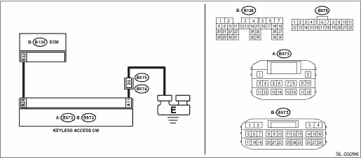
Wiring diagram:
Push button start system Push Button Start System > WIRING DIAGRAM">
| STEP | CHECK | YES | NO |
1.CHECK LAN SYSTEM.
Inspect LAN system. Basic Diagnostic Procedure > PROCEDURE">
Is LAN system normal?
Diagnostic Procedure with Diagnostic Trouble Code (DTC) > DTC B2276 ACC RELAY OFF SIGNAL">Go to Step 2.
Perform the inspection according to the diagnosis for LAN system.
2.CHECK HARNESS.
1) Disconnect the keyless access CM connector and ECM connector.
2) Using a tester, measure the resistance between the keyless access CM connector and ECM.
Connector & terminal
(B573) No. 28 — (B135) No. 32:
Is the resistance less than 1 ??
Diagnostic Procedure with Diagnostic Trouble Code (DTC) > DTC B2276 ACC RELAY OFF SIGNAL">Go to Step 3.
Repair or replace the open circuit of harness.
3.CHECK HARNESS.
Using a tester, measure the resistance between the keyless access CM connector and chassis ground.
Connector & terminal
(B573) No. 28 — Chassis ground:
Is the resistance 10 k? or more?
Diagnostic Procedure with Diagnostic Trouble Code (DTC) > DTC B2276 ACC RELAY OFF SIGNAL">Go to Step 4.
Repair or replace the short circuit of the harness.
4.CHECK HARNESS.
Using a tester, measure the resistance between the keyless access CM connector and chassis ground.
Connector & terminal
(B572) No. 11 — Chassis ground:
Is the resistance less than 1 ??
Diagnostic Procedure with Diagnostic Trouble Code (DTC) > DTC B2276 ACC RELAY OFF SIGNAL">Go to Step 5.
Repair or replace the open circuit of harness.
5.CHECK KEYLESS ACCESS CM.
1) Connect the keyless access CM connector and ECM connector.
2) Using a tester, measure the voltage between terminals of the keyless access CM connector when the push button ignition switch is pressed, while depressing the brake pedal with the shift lever in the “P” range.
Connector & terminal
(B573) No. 28 (+) — (B572) No. 11 (−):
Is the voltage 9.5 — 16 V > 1 V or less?
Replace the keyless access CM. Keyless Access CM">
Replace the ECM. Engine Control Module (ECM) > REMOVAL">
 Dtc b2275 engine start request control circuit
KEYLESS ACCESS WITH PUSH BUTTON START SYSTEM (DIAGNOSTICS) > Diagnostic Procedure with Diagnostic Trouble Code (DTC)DTC B2275 ENGINE START REQUEST CONTROL CIRCUITDTC detecting condition:• Whe ...
 Dtc u0122 lost communication with vehicle dynamics control module
KEYLESS ACCESS WITH PUSH BUTTON START SYSTEM (DIAGNOSTICS) > Diagnostic Procedure with Diagnostic Trouble Code (DTC)DTC U0122 LOST COMMUNICATION WITH VEHICLE DYNAMICS CONTROL MODULEDetected when CA ...
Other materials:
Cruise control (if equipped)
NOTE
For models with EyeSight system:
Refer to the Owner's Manual supplement
for the EyeSight system.
Cruise control enables you to maintain a
constant vehicle speed without holding
your foot on the accelerator pedal and it is
operative when the vehicle speed is 25
mph (40 km/h) or more.
WA ...
Dtc b1761 occupant detection sensor mat liquid coating
OCCUPANT DETECTION SYSTEM (DIAGNOSTICS) > Diagnostic Procedure with Diagnostic Trouble Code (DTC)DTC B1761 OCCUPANT DETECTION SENSOR MAT LIQUID COATINGDIAGNOSIS START CONDITION:Ignition voltage is 8 V to 16 V.DTC DETECTING CONDITION:• Occupant detection sensor is spattered with fluid.• ...
List
EyeSight (DIAGNOSTICS) > ECM Cancel Code(s) DisplayLIST• List of ECM cruise control cancel code(s)When the cruise control is cancelled, the ECM outputs the following cancel codes.Cancel codeItemContents of diagnosisReference11Main switchMain switch of the EyeSight steering switch is turned ...
