Subaru Crosstrek Service Manual: Removal
BRAKE > Brake Pedal
REMOVAL
1. CVT MODEL
CAUTION:
Before handling the airbag system components, always refer to “CAUTION” of “General Description” in “AIRBAG SYSTEM”. General Description > CAUTION">
1. Disconnect the ground cable from battery and wait for at least 60 seconds before starting work. NOTE">
2. Remove the cover assembly - instrument panel LWR driver. Instrument Panel Lower Cover > REMOVAL">
3. Remove the knee airbag module. Knee Airbag Module > REMOVAL">
4. Remove the universal joint assembly - steering. Universal Joint > REMOVAL">
CAUTION:
To prevent damage to the universal joint assembly - steering and improper steering effort, make sure to remove the universal joint assembly - steering.
5. Remove the column assembly - steering. Steering Column > REMOVAL">
6. Remove the brake pedal assembly.
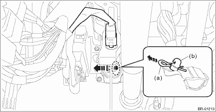
(1) Disconnect the stop light switch connector.
(2) Remove the snap pin (a) and clevis pin (b), and remove the operating rod from the brake pedal.
CAUTION:
• Be careful not to apply excessive force to the operating rod when handling the operating rod.
The angle may change by ±3°, and it may result in damage to power piston cylinder.
• Do not change the push rod length.
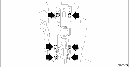
(3) Remove the bolt and nut, and then detach the brake pedal assembly.
2. MT MODEL
NOTE:
Brake pedal is integrated with the clutch pedal.
For removal procedures of the brake pedal, refer to Clutch section. Clutch Pedal > REMOVAL">
 Inspection
BRAKE > Brake PedalINSPECTION1. Move the pad - brake pedal in a horizontal direction with a force of approx. 10 N (1 kgf, 2 lbf), and check that the pedal deflection is in the range of specificatio ...
 Installation
BRAKE > Brake PedalINSTALLATIONCAUTION:Before handling the airbag system components, always refer to “CAUTION” of “General Description” in “AIRBAG SYSTEM”. Gene ...
Other materials:
Installation
SECURITY AND LOCKS > Keyless Access CMINSTALLATIONCAUTION:• When the control module related to immobilizer has been replaced, be sure to perform the registration of immobilizer system. For detailed operation procedure, refer to “Type D” described in “REGISTRATION MANUAL FO ...
Inspection
EMISSION CONTROL (AUX. EMISSION CONTROL DEVICES)(H4DO) > EGR Control ValveINSPECTION1. Check that the EGR control valve has no deformation, cracks or other damages.2. Measure the resistance between EGR control valve terminals.Terminal No.Standard2 and 122±2 ?2 and 322±2 ?5 and 422±2 ?5 and 622 ...
Interior light off delay timer setting
1. Perform the preparation steps according
to "Preparation for car settings"
2. Operate the " " or "
" switch to
select the "Interior Light" item. Then push
the button.
3. The current setting will be displayed.
Push the button to enter the
selection
mode.
4. Select ...
