Subaru Crosstrek Service Manual: Dtc b1012 battery backup power supply
BODY CONTROL SYSTEM (DIAGNOSTICS) > Diagnostic Procedure with Diagnostic Trouble Code (DTC)
DTC B1012 BATTERY BACKUP POWER SUPPLY
DTC detecting condition:
Voltage failure caused by poor contact of battery power supply backup circuits
Trouble symptom:
Illuminations for the keyless entry, map light, luggage light, trunk light, room light, and ignition switch do not turn on.
NOTE:
When B1011 BATTERY CONTROL POWER SUPPLY is output at the same time, all the function of body integrated unit may not operate.
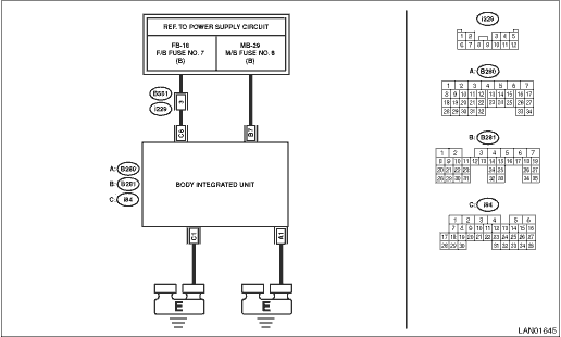
Wiring diagram:
Immobilizer system Immobilizer System > WIRING DIAGRAM">
| STEP | CHECK | YES | NO |
1.CHECK DTC.
Read the DTC of body integrated unit using Subaru Select Monitor. Read Diagnostic Trouble Code (DTC)">
Is B1012 current malfunction?
Diagnostic Procedure with Diagnostic Trouble Code (DTC) > DTC B1012 BATTERY BACKUP POWER SUPPLY">Go to Step 2.
Diagnostic Procedure with Diagnostic Trouble Code (DTC) > DTC B1012 BATTERY BACKUP POWER SUPPLY">Go to Step 5.
2.CHECK DTC.
1) Turn the ignition switch to OFF.
2) Disconnect and then connect the body integrated unit connector.
3) Wait approx. 2 minutes.
4) Turn the ignition switch to ON.
5) Read the DTC of body integrated unit using Subaru Select Monitor. Read Diagnostic Trouble Code (DTC)">
Is B1012 current malfunction?
Diagnostic Procedure with Diagnostic Trouble Code (DTC) > DTC B1012 BATTERY BACKUP POWER SUPPLY">Go to Step 3.
Diagnostic Procedure with Diagnostic Trouble Code (DTC) > DTC B1012 BATTERY BACKUP POWER SUPPLY">Go to Step 5.
3.CHECK FUSE.
1) Turn the ignition switch to OFF.
2) Check the fuse.
Is the fuse OK?
Diagnostic Procedure with Diagnostic Trouble Code (DTC) > DTC B1012 BATTERY BACKUP POWER SUPPLY">Go to Step 4.
Replace the defective fuse.
4.CHECK HARNESS.
1) Disconnect the body integrated unit connector.
2) Using the tester, measure the voltage between terminals.
Connector & terminal
(B281) No. 7 (+) — Chassis ground (−):
Is the voltage 8.5 — 16.5 V?
Replace the body integrated unit. Body Integrated Unit">
Repair the harness between body integrated unit and fuse.
5.CHECK CONNECTOR.
1) Turn the ignition switch to OFF.
2) Disconnect the body integrated unit connector.
Is there poor contact of connector?
Repair or replace the poor contact of connector.
Even if DTC is displayed, the circuit has returned to a normal condition at this time. Reproduce the failure, and then perform the diagnosis again.
NOTE:
In this case, temporary poor contact of connector, temporary open or short circuit of harness may be the cause.
 Dtc b1011 battery control power supply
BODY CONTROL SYSTEM (DIAGNOSTICS) > Diagnostic Procedure with Diagnostic Trouble Code (DTC)DTC B1011 BATTERY CONTROL POWER SUPPLYDTC detecting condition:• Voltage failure caused by poor conta ...
 Dtc b1013 ignition power
BODY CONTROL SYSTEM (DIAGNOSTICS) > Diagnostic Procedure with Diagnostic Trouble Code (DTC)DTC B1013 IGNITION POWERDTC detecting condition:Voltage failure caused by poor contact of IGN power supply ...
Other materials:
Installation
CONTROL SYSTEMS > AT Shift Lock Solenoid and “P” Range SwitchINSTALLATIONInstall in the reverse order of removal.NOTE:Insert the solenoid unit terminals to the harness connector.(A)Solenoid unit (color code: blue)(B)Solenoid unit (color code: black) ...
Removal
MANUAL TRANSMISSION AND DIFFERENTIAL(5MT) > Manual Transmission AssemblyREMOVAL1. Disconnect the ground cable from battery.2. Remove the clip (A) from the air intake boot.3. Loosen the clamp (B) connecting the air intake boot and air cleaner case (rear).4. Loosen the clamp (C) which connects the ...
Dtc p0420 catalyst system efficiency below threshold bank 1
ENGINE (DIAGNOSTICS)(H4DO) > Diagnostic Procedure with Diagnostic Trouble Code (DTC)DTC P0420 CATALYST SYSTEM EFFICIENCY BELOW THRESHOLD BANK 1DTC detecting condition:Detected when two consecutive driving cycles with fault occur.Trouble symptom:• Engine stall• Idle mixture is out of s ...
