Subaru Crosstrek Service Manual: Dtc b1011 battery control power supply
BODY CONTROL SYSTEM (DIAGNOSTICS) > Diagnostic Procedure with Diagnostic Trouble Code (DTC)
DTC B1011 BATTERY CONTROL POWER SUPPLY
DTC detecting condition:
• Voltage failure caused by poor contact of battery power supply control circuit
• Battery voltage of body integrated unit is not within the range of 8.5 — 16.5 V.
Trouble symptom:
Functions of body integrated unit stop.
NOTE:
When DTC B1012 BATTERY BACKUP POWER SUPPLY is output at the same time, all the function of body integrated unit may not operate.
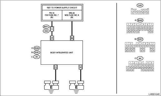
Wiring diagram:
Immobilizer system Immobilizer System > WIRING DIAGRAM">
| STEP | CHECK | YES | NO |
1.CHECK DTC.
Read the DTC of body integrated unit using Subaru Select Monitor. Read Diagnostic Trouble Code (DTC)">
Is B1011 current malfunction?
Diagnostic Procedure with Diagnostic Trouble Code (DTC) > DTC B1011 BATTERY CONTROL POWER SUPPLY">Go to Step 2.
Diagnostic Procedure with Diagnostic Trouble Code (DTC) > DTC B1011 BATTERY CONTROL POWER SUPPLY">Go to Step 5.
2.CHECK DTC.
1) Turn the ignition switch to OFF.
2) Disconnect and then connect the body integrated unit connector.
3) Wait approx. 2 minutes.
4) Turn the ignition switch to ON.
5) Read the DTC of body integrated unit using Subaru Select Monitor. Read Diagnostic Trouble Code (DTC)">
Is B1011 current malfunction?
Diagnostic Procedure with Diagnostic Trouble Code (DTC) > DTC B1011 BATTERY CONTROL POWER SUPPLY">Go to Step 3.
Diagnostic Procedure with Diagnostic Trouble Code (DTC) > DTC B1011 BATTERY CONTROL POWER SUPPLY">Go to Step 5.
3.CHECK FUSE.
1) Turn the ignition switch to OFF.
2) Check the fuse.
Is the fuse OK?
Diagnostic Procedure with Diagnostic Trouble Code (DTC) > DTC B1011 BATTERY CONTROL POWER SUPPLY">Go to Step 4.
Replace the defective fuse.
4.CHECK HARNESS.
1) Disconnect the body integrated unit connector.
2) Using the tester, measure the voltage between terminals.
Connector & terminal
(i84) No. 6 (+) — Chassis ground (−):
Is the voltage 8.5 — 16.5 V?
Replace the body integrated unit. Body Integrated Unit">
Repair the harness between body integrated unit and fuse.
5.CHECK CONNECTOR.
1) Turn the ignition switch to OFF.
2) Disconnect the body integrated unit connector.
Is there poor contact of connector?
Repair or replace the poor contact of connector.
Even if DTC is displayed, the circuit has returned to a normal condition at this time. Reproduce the failure, and then perform the diagnosis again.
NOTE:
In this case, temporary poor contact of connector, temporary open or short circuit of harness may be the cause.
 Dtc b1010 body control system (biu) malfunction
BODY CONTROL SYSTEM (DIAGNOSTICS) > Diagnostic Procedure with Diagnostic Trouble Code (DTC)DTC B1010 BODY CONTROL SYSTEM (BIU) MALFUNCTIONDTC DETECTING CONDITION:System error in body integrated uni ...
 Dtc b1012 battery backup power supply
BODY CONTROL SYSTEM (DIAGNOSTICS) > Diagnostic Procedure with Diagnostic Trouble Code (DTC)DTC B1012 BATTERY BACKUP POWER SUPPLYDTC detecting condition:Voltage failure caused by poor contact of bat ...
Other materials:
Removal
FRONT SUSPENSION > Front StabilizerREMOVAL1. Lift up the vehicle, and then remove the left and right front wheels.2. Remove the under cover - front. Front Under Cover > REMOVAL">3. Remove the front crossmember support. Front Crossmember Support Plate > REMOVAL">4. Remove t ...
Removal
CLUTCH SYSTEM > Operating CylinderREMOVALCAUTION:Brake fluid spilled on the vehicle body will harm the paint surface; therefore, wash it off with water and wipe clean quickly if spilled.1. Disconnect the ground cable from battery.2. Remove the clip (A) from the air intake boot.3. Loosen the clamp ...
Removal
EXTERIOR/INTERIOR TRIM > Rear Gate GarnishREMOVAL1. Disconnect the ground cable from battery. NOTE">2. Remove the trim panel - rear gate. Rear Gate Trim > REMOVAL">3. Remove the arm assembly - rear wiper.(1) Remove the cover - rear wiper arm.(2) Remove the nut, and remove the ...
