Subaru Crosstrek Service Manual: Dtc b1013 ignition power
BODY CONTROL SYSTEM (DIAGNOSTICS) > Diagnostic Procedure with Diagnostic Trouble Code (DTC)
DTC B1013 IGNITION POWER
DTC detecting condition:
Voltage failure caused by poor contact of IGN power supply circuits
Trouble symptom:
Symptoms such as shift lock or wiper not operating may occur.
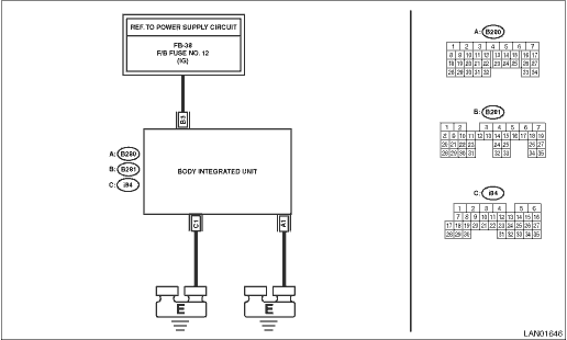
Wiring diagram:
Shift lock control system Shift Lock Control System > WIRING DIAGRAM">
| STEP | CHECK | YES | NO |
1.CHECK DTC.
Read the DTC of body integrated unit using Subaru Select Monitor. Read Diagnostic Trouble Code (DTC)">
Is B1013 current malfunction?
Diagnostic Procedure with Diagnostic Trouble Code (DTC) > DTC B1013 IGNITION POWER">Go to Step 2.
Diagnostic Procedure with Diagnostic Trouble Code (DTC) > DTC B1013 IGNITION POWER">Go to Step 5.
2.CHECK DTC.
1) Turn the ignition switch to OFF.
2) Disconnect and then connect the body integrated unit connector.
3) Wait approx. 2 minutes.
4) Turn the ignition switch to ON.
5) Read the DTC of body integrated unit using Subaru Select Monitor. Read Diagnostic Trouble Code (DTC)">
Is B1013 current malfunction?
Diagnostic Procedure with Diagnostic Trouble Code (DTC) > DTC B1013 IGNITION POWER">Go to Step 3.
Diagnostic Procedure with Diagnostic Trouble Code (DTC) > DTC B1013 IGNITION POWER">Go to Step 5.
3.CHECK FUSE.
1) Turn the ignition switch to OFF.
2) Check the fuse.
Is the fuse OK?
Diagnostic Procedure with Diagnostic Trouble Code (DTC) > DTC B1013 IGNITION POWER">Go to Step 4.
Replace the defective fuse.
4.CHECK HARNESS.
1) Disconnect the body integrated unit connector.
2) Using the tester, measure the voltage between terminals.
Connector & terminal
(B281) No. 3 (+) — Chassis ground (−):
Is the voltage 8.5 — 16.5 V?
Replace the body integrated unit. Body Integrated Unit">
Repair the harness between body integrated unit and fuse.
5.CHECK CONNECTOR.
1) Turn the ignition switch to OFF.
2) Disconnect the body integrated unit connector.
Is there poor contact of connector?
Repair or replace the poor contact of connector.
Even if DTC is displayed, the circuit has returned to a normal condition at this time. Reproduce the failure, and then perform the diagnosis again.
NOTE:
In this case, temporary poor contact of connector, temporary open or short circuit of harness may be the cause.
 Dtc b1012 battery backup power supply
BODY CONTROL SYSTEM (DIAGNOSTICS) > Diagnostic Procedure with Diagnostic Trouble Code (DTC)DTC B1012 BATTERY BACKUP POWER SUPPLYDTC detecting condition:Voltage failure caused by poor contact of bat ...
 Dtc b1014 acc power
BODY CONTROL SYSTEM (DIAGNOSTICS) > Diagnostic Procedure with Diagnostic Trouble Code (DTC)DTC B1014 ACC POWERDTC detecting condition:Voltage failure caused by poor contact of ACC power supply circ ...
Other materials:
Inspection
DRIVE SHAFT SYSTEM > Propeller ShaftINSPECTIONCheck the propeller shaft with the propeller shaft installed to the vehicle.1. Remove the front exhaust pipe. Front Exhaust Pipe > REMOVAL">2. Remove the center exhaust pipe, rear exhaust pipe, and muffler.• Center exhaust pipe & ...
Installation
SECURITY AND LOCKS > Front Hood Lock AssemblyINSTALLATION1. Before installation, check the following items.• Is the cable deformed?• Grease is applied sufficiently to cable joints.If grease is insufficient, add it as necessary before assembling the cable.2. Install each part in the re ...
Disabling keyless access function
WARNING
If you wear an implanted pacemaker
or an implanted defibrillator, perform
the procedure described in
"By operating the driver's door"
2-18 to disable the keyless access
function. If you perform the procedure
described in "By operating the
access key" 2-18, the operation of
an implan ...
