Subaru Crosstrek Service Manual: Dtc b1014 acc power
BODY CONTROL SYSTEM (DIAGNOSTICS) > Diagnostic Procedure with Diagnostic Trouble Code (DTC)
DTC B1014 ACC POWER
DTC detecting condition:
Voltage failure caused by poor contact of ACC power supply circuit
Trouble symptom:
DRL may not illuminate.
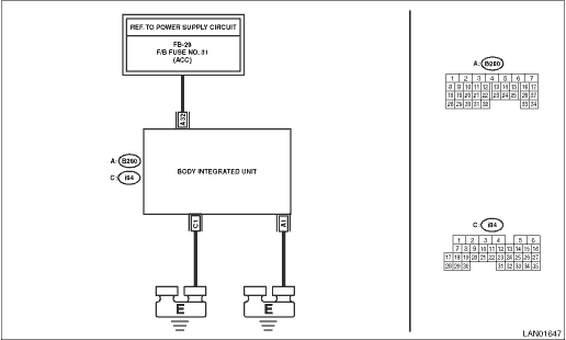
Wiring diagram:
Shift lock control system Shift Lock Control System > WIRING DIAGRAM">
| STEP | CHECK | YES | NO |
1.CHECK DTC.
Read the DTC of body integrated unit using Subaru Select Monitor. Read Diagnostic Trouble Code (DTC)">
Is B1014 current malfunction?
Diagnostic Procedure with Diagnostic Trouble Code (DTC) > DTC B1014 ACC POWER">Go to Step 2.
Diagnostic Procedure with Diagnostic Trouble Code (DTC) > DTC B1014 ACC POWER">Go to Step 5.
2.CHECK DTC.
1) Turn the ignition switch to OFF.
2) Disconnect and then connect the body integrated unit connector.
3) Wait approx. 2 minutes.
4) Turn the ignition switch to ON.
5) Read the DTC of body integrated unit using Subaru Select Monitor. Read Diagnostic Trouble Code (DTC)">
Is B1014 current malfunction?
Diagnostic Procedure with Diagnostic Trouble Code (DTC) > DTC B1014 ACC POWER">Go to Step 3.
Diagnostic Procedure with Diagnostic Trouble Code (DTC) > DTC B1014 ACC POWER">Go to Step 5.
3.CHECK FUSE.
1) Turn the ignition switch to OFF.
2) Check the fuse.
Is the fuse OK?
Diagnostic Procedure with Diagnostic Trouble Code (DTC) > DTC B1014 ACC POWER">Go to Step 4.
Replace the defective fuse.
4.CHECK HARNESS.
1) Disconnect the body integrated unit connector.
2) Using the tester, measure the voltage between terminals.
Connector & terminal
(B280) No. 32 (+) — Chassis ground (−):
Is the voltage 8.5 — 16.5 V?
Replace the body integrated unit. Body Integrated Unit">
Repair the harness between body integrated unit and fuse.
5.CHECK CONNECTOR.
1) Turn the ignition switch to OFF.
2) Disconnect the body integrated unit connector.
Is there poor contact of connector?
Repair or replace the poor contact of connector.
Even if DTC is displayed, the circuit has returned to a normal condition at this time. Reproduce the failure, and then perform the diagnosis again.
NOTE:
In this case, temporary poor contact of connector, temporary open or short circuit of harness may be the cause.
 Dtc b1013 ignition power
BODY CONTROL SYSTEM (DIAGNOSTICS) > Diagnostic Procedure with Diagnostic Trouble Code (DTC)DTC B1013 IGNITION POWERDTC detecting condition:Voltage failure caused by poor contact of IGN power supply ...
 Dtc b1015 key interlock circuit
BODY CONTROL SYSTEM (DIAGNOSTICS) > Diagnostic Procedure with Diagnostic Trouble Code (DTC)DTC B1015 KEY INTERLOCK CIRCUITDTC detecting condition:Ground short of key interlock circuitTrouble sympto ...
Other materials:
Rear window wiper blade rubber
1. Pull out the end of the blade rubber
assembly to unlock it from the plastic
support.
2. Pull the blade rubber assembly out of
the plastic support.
1) Metal spines
3. If the new blade rubber is not provided
with two metal spines, remove the metal
spines from the old blade rubbe ...
Keyless access system Wiring diagram
WIRING SYSTEM > Keyless Access SystemWIRING DIAGRAM ...
Front seats
WARNING
Never adjust the seat while driving
to avoid loss of vehicle control
and personal injury.
Before adjusting the seat, make
sure the hands and feet of rear
seat passengers and cargo are
clear of the adjusting mechanism.
After adjusting the seat, push it
slightly to make sur ...
