Subaru Crosstrek Service Manual: Dtc b1015 key interlock circuit
BODY CONTROL SYSTEM (DIAGNOSTICS) > Diagnostic Procedure with Diagnostic Trouble Code (DTC)
DTC B1015 KEY INTERLOCK CIRCUIT
DTC detecting condition:
Ground short of key interlock circuit
Trouble symptom:
Key interlock does not keep lock condition.
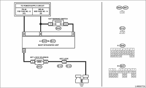
Wiring diagram:
Shift lock control system Shift Lock Control System > WIRING DIAGRAM">
| STEP | CHECK | YES | NO |
1.CHECK DTC.
1) Insert the ignition key.
2) Turn the ignition switch to ON.
3) Shift to the Neutral range.
4) Shift into P range.
5) Shift to the Neutral range.
6) Shift into P range.
7) Shift to the Neutral range.
8) Read the DTC of body integrated unit using Subaru Select Monitor. Read Diagnostic Trouble Code (DTC)">
Is B1015 current malfunction?
Diagnostic Procedure with Diagnostic Trouble Code (DTC) > DTC B1015 KEY INTERLOCK CIRCUIT">Go to Step 2.
Diagnostic Procedure with Diagnostic Trouble Code (DTC) > DTC B1015 KEY INTERLOCK CIRCUIT">Go to Step 8.
2.CHECK DTC.
1) Shift the select lever to P range.
2) Remove the ignition key.
3) Disconnect the key actuator connector (B557) and body integrated unit connector (B281).
4) Connect the disconnected connectors.
5) Insert the ignition key.
6) Turn the ignition switch to ON and shift into Neutral.
7) Read the DTC of body integrated unit using Subaru Select Monitor. Read Diagnostic Trouble Code (DTC)">
Is B1015 current malfunction?
Diagnostic Procedure with Diagnostic Trouble Code (DTC) > DTC B1015 KEY INTERLOCK CIRCUIT">Go to Step 3.
Diagnostic Procedure with Diagnostic Trouble Code (DTC) > DTC B1015 KEY INTERLOCK CIRCUIT">Go to Step 8.
3.CHECK KEY ACTUATOR.
1) Turn the ignition switch to OFF.
2) Disconnect the key actuator connector (B557).
3) Measure the resistance between key actuator connectors.
Terminals
No. 1 — No. 2:
Is the resistance 103 — 115 ??
Diagnostic Procedure with Diagnostic Trouble Code (DTC) > DTC B1015 KEY INTERLOCK CIRCUIT">Go to Step 4.
Replace the key actuator. Key Lock Cylinders">
4.CHECK KEY ACTUATOR.
Connect the battery terminals to the key actuator.
Terminals
No. 2 — Positive terminal:
No. 1 — Ground terminal:
Is the actuator activated and then key locked?
Diagnostic Procedure with Diagnostic Trouble Code (DTC) > DTC B1015 KEY INTERLOCK CIRCUIT">Go to Step 5.
Replace the key actuator. Key Lock Cylinders">
5.CHECK HARNESS.
1) Disconnect the body integrated unit connector (B281).
2) Measure the resistance between body integrated unit and key actuator using tester.
Connector & terminal
(B557) No. 1 — (B281) No. 4:
Is the resistance less than 10 ??
Diagnostic Procedure with Diagnostic Trouble Code (DTC) > DTC B1015 KEY INTERLOCK CIRCUIT">Go to Step 6.
Repair or replace the open circuit of harness.
6.CHECK HARNESS.
Measure the resistance between body integrated unit and chassis ground using tester.
Connector & terminal
(B281) No. 4 — Chassis ground:
Is the resistance 1 M? or more?
Diagnostic Procedure with Diagnostic Trouble Code (DTC) > DTC B1015 KEY INTERLOCK CIRCUIT">Go to Step 7.
Repair or replace the short circuit of the harness.
7.CHECK HARNESS.
1) Connect the body integrated unit.
2) Turn the ignition switch to ON.
3) Measure the voltage between body integrated unit and chassis ground using tester.
Connector & terminal
(B281) No. 4 (+) — Chassis ground (−):
Is the voltage 6 V or more?
Diagnostic Procedure with Diagnostic Trouble Code (DTC) > DTC B1015 KEY INTERLOCK CIRCUIT">Go to Step 8.
Replace the body integrated unit. Body Integrated Unit">
8.CHECK CONNECTOR.
1) Turn the ignition switch to OFF.
2) Disconnect the body integrated unit connector (B281) and key actuator connector (B557).
Is there poor contact at disconnected connector terminal?
Repair the terminal where poor contact exists, or replace harness.
Even if DTC is displayed, the circuit has returned to a normal condition at this time. Reproduce the failure, and then perform the diagnosis again.
NOTE:
In this case, temporary poor contact of connector, temporary open or short circuit of harness may be the cause.
 Dtc b1014 acc power
BODY CONTROL SYSTEM (DIAGNOSTICS) > Diagnostic Procedure with Diagnostic Trouble Code (DTC)DTC B1014 ACC POWERDTC detecting condition:Voltage failure caused by poor contact of ACC power supply circ ...

Other materials:
Stopping engine
Stop the vehicle completely.
Move the select lever to the "P"
position.
Press the push-button ignition switch.
The engine will stop, and the power will be
switched off.
WARNING
Do not touch the push-button
ignition switch during driving.
When the push-button ignition
switch is ...
Read diagnostic trouble code (dtc) Operation
LAN SYSTEM (DIAGNOSTICS) > Read Diagnostic Trouble Code (DTC)OPERATION1. On «Start» display, select «Diagnosis».2. On «Vehicle selection» display, input the target vehicle information and select «Confirmed».3. On «Main Menu» display, select «All diagnosis code».NOTE:• For detail ...
Component
FRONT SUSPENSION > General DescriptionCOMPONENT1. FRONT SUSPENSION(1)Front crossmember COMPL(14)Bushing rear - front arm(27)Clip(2)Flange bolt(15)Stud bolt (3)Front crossmember support(16)Stopper - front arm bushing rearTightening torque: N·m (kgf-m, ft-lb)(4)Front stabilizer(17)AdapterT1 ...
