Subaru Crosstrek Service Manual: Inspection
INSTRUMENTATION/DRIVER INFO > Steering Switch
INSPECTION
1. Measure the resistance between switch terminals.
Preparation tool:
Circuit tester
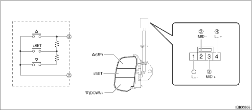
Terminal No. | Inspection conditions | Standard | |
3 — 2 |
i/SET
| All OFF | Approx. 1 M? or more |
| ON | Less than 1 ? | |
i/SET | ON | Approx. 1,000 ? | |
| ON | Approx. 3,670 ? | |
 (UP)
(UP) (DOWN)
2. Apply battery voltage between the connector terminals to check lighting condition of illumination inside the switch.
Terminal No. | Inspection conditions | Specification |
4 (+) — 1 (−) | Apply battery voltage. | Light ON |
3. Replace the MID switch if the inspection result is not within the standard value.
 Steering switch
...
 Removal
INSTRUMENTATION/DRIVER INFO > Steering SwitchREMOVALCAUTION:Before handling the airbag system components, refer to “CAUTION” of “General Description” in “AIRBAG SYSTEM ...
Other materials:
Removal
SECURITY AND LOCKS > Security Control ModuleREMOVALCAUTION:• Before handling the airbag system components, refer to “CAUTION” of “General Description” in “AIRBAG SYSTEM”. General Description > CAUTION">• Do not allow harness and connecto ...
Control unit Note
CRUISE CONTROL SYSTEM > Control UnitNOTESystem control of the cruise control is performed by each module. For procedure, refer to the following sections.• Engine control module (ECM): Engine Control Module (ECM)">• Transmission control module (TCM): Transmission Control Modu ...
Dtc p0390 camshaft position sensor "b" circuit bank 2
ENGINE (DIAGNOSTICS)(H4DO) > Diagnostic Procedure with Diagnostic Trouble Code (DTC)DTC P0390 CAMSHAFT POSITION SENSOR "B" CIRCUIT BANK 2DTC DETECTING CONDITION:Immediately at fault recognitionTROUBLE SYMPTOM:• Engine stall• Failure of engine to startCAUTION:After servicing ...
