Subaru Crosstrek Service Manual: Component
CLUTCH SYSTEM > General Description
COMPONENT
1. CLUTCH ASSEMBLY
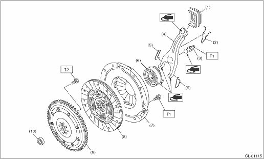
(1) | Dust cover | (6) | Release bearing | Tightening torque: N·m (kgf-m, ft-lb) | |
(2) | Lever spring | (7) | Clutch cover | T1: | 16 (1.6, 11.8) |
(3) | Pivot | (8) | Clutch disc | T2: | Flywheel > INSTALLATION"> |
(4) | Release lever | (9) | Flexible flywheel | ||
(5) | Clip | (10) | Pilot bearing | ||

2. CLUTCH PIPE AND HOSE
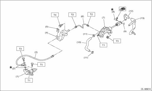
(1) | Operating cylinder | (8) | Clevis pin | Tightening torque: N·m (kgf-m, ft-lb) | |
(2) | Gasket | (9) | Snap pin | T1: | 7.8 (0.8, 5.8) |
(3) | Clutch hose | (10) | Tank hose | T2: | 15 (1.5, 11.1) |
(4) | Clutch hose bracket | (11) | Clamp | T3: | 18 (1.8, 13.3) |
(5) | Clamp | (12) | Lever | T4: | 25 (2.5, 18.4) |
(6) | Clutch pipe | (13) | Pedal | T5: | 37 (3.8, 27.3) |
(7) | Master cylinder ASSY | ||||
3. MASTER CYLINDER
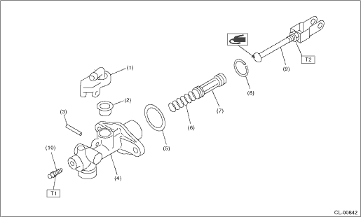
(1) | Nipple | (6) | Return spring | Tightening torque: N·m (kgf-m, ft-lb) | |
(2) | Oil seal | (7) | Piston | T1: | 7.8 (0.8, 5.8) |
(3) | Straight pin | (8) | Piston stop ring | T2: | 10 (1.0, 7.4) |
(4) | Master cylinder | (9) | Push rod ASSY | ||
(5) | Seat | (10) | Bleeder screw | ||
4. OPERATING CYLINDER
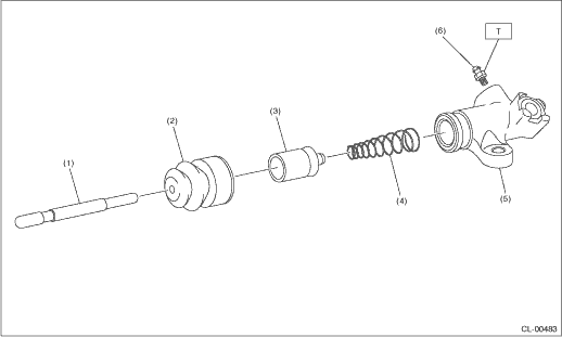
(1) | Push rod | (4) | Piston spring | Tightening torque: N·m (kgf-m, ft-lb) | |
(2) | Boot | (5) | Operating cylinder | T: | 7.8 (0.8, 5.8) |
(3) | Piston | (6) | Bleeder screw | ||
5. CLUTCH PEDAL
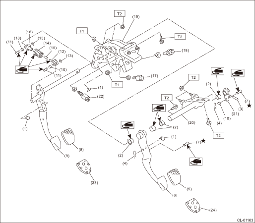
(1) | Stopper | (11) | Clutch clevis pin | (21) | Lever |
(2) | Pedal bushing | (12) | Assist rod A | (22) | Clutch start switch |
(3) | Spring pin | (13) | Clip | (23) | Clutch pedal pad (sport type) |
(4) | Snap pin | (14) | Assist spring | (24) | Brake pedal pad (sport type) |
(5) | Brake pedal pad (normal type) | (15) | Assist bushing | ||
(6) | Brake pedal | (16) | Assist rod B | Tightening torque: N·m (kgf-m, ft-lb) | |
(7) | Clevis pin | (17) | Clutch switch | T1: | 8 (0.8, 5.9) |
(8) | Clutch pedal pad (normal type) | (18) | Stop light switch | T2: | 18 (1.8, 13.3) |
(9) | Clutch pedal | (19) | Pedal bracket | ||
(10) | Bushing C | (20) | Clutch master cylinder bracket | ||
 Specification
CLUTCH SYSTEM > General DescriptionSPECIFICATIONModel2.0 LTransmission type5MTClutch coverTypePush typeDiaphragm set loadN (kgf, lbf)5,688 (580, 1,279)Clutch discFacing materialWoven (non-asbestos) ...
 Preparation tool
CLUTCH SYSTEM > General DescriptionPREPARATION TOOL1. SPECIAL TOOLILLUSTRATIONTOOL NUMBERDESCRIPTIONREMARKS498497100CRANKSHAFT STOPPERUsed for stopping rotation of the flywheel.499747100CLUTCH DISC ...
Other materials:
Removal
FUEL INJECTION (FUEL SYSTEMS)(H4DO) > Crankshaft Position SensorREMOVAL1. Disconnect the ground cable from battery.2. Remove the clip (A), and loosen the clamps (B) and (C) securing the air intake boot.3. Remove the air intake boot from the air cleaner case (rear) and throttle body, and move the ...
Dtc u0100 lost communication with ecm/pcm a
INSTRUMENTATION/DRIVER INFO (DIAGNOSTICS) > Diagnostic Procedure with Diagnostic Trouble Code (DTC)DTC U0100 LOST COMMUNICATION WITH ECM/PCM “A”Detected when CAN data from the engine control module (ECM) does not arrive.NOTE:Perform the diagnosis for LAN system. Basic Diagnostic Proc ...
Dtc p0366 camshaft position sensor "b" circuit range/performance bank 1
ENGINE (DIAGNOSTICS)(H4DO) > Diagnostic Procedure with Diagnostic Trouble Code (DTC)DTC P0366 CAMSHAFT POSITION SENSOR "B" CIRCUIT RANGE/PERFORMANCE BANK 1NOTE:For the diagnostic procedure, refer to DTC P0365. Diagnostic Procedure with Diagnostic Trouble Code (DTC) > DTC P0365 CAMSH ...
