Subaru Crosstrek Service Manual: Installation
MECHANICAL(H4DO) > Timing Chain Assembly
INSTALLATION
1. TIMING CHAIN LH
NOTE:
• Be careful that the foreign matter is not into or onto the assembled component during installation.
• Apply engine oil to all component parts of the timing chain.
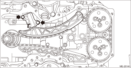
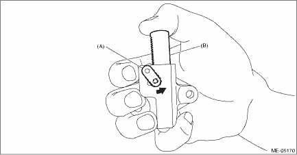
1. Prepare to attach the chain tensioner LH.
(1) Move the link plate (A) in the direction of arrow to press in the plunger (B).
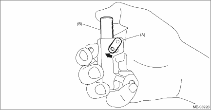
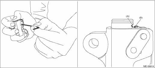
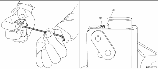
(2) With a 1.3 mm (0.05 in) dia. stopper pin or a 1.3 mm dia. hex wrench inserted into the stopper pin hole, secure the plunger.
NOTE:
If the stopper pin hole on the link plate and the stopper pin hole on the chain tensioner are not aligned, check that the first notch of plunger rack (A) is engaged with the stopper tooth (B). If not engaged, retract the plunger a little so that the first notch of plunger rack (A) is engaged with the stopper tooth (B).
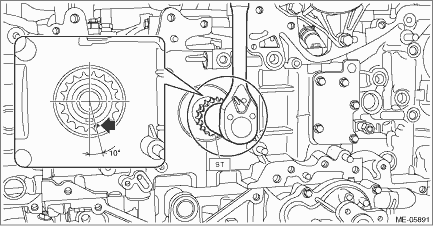
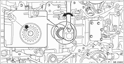
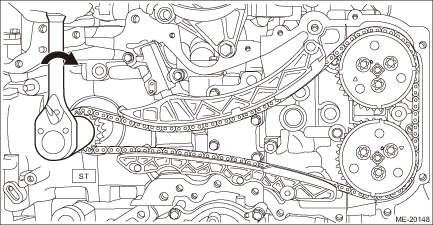
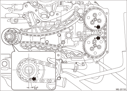
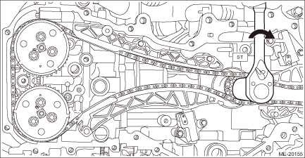
2. Check that the crank sprocket is located at the position shown in the figure. If not aligned, using ST turn the crankshaft to align the crank sprocket alignment mark to the position shown in the figure.
NOTE:
This procedure is required to prevent the valve and piston contacting with each other in the next step.
| ST 18252AA000 | CRANKSHAFT SOCKET |
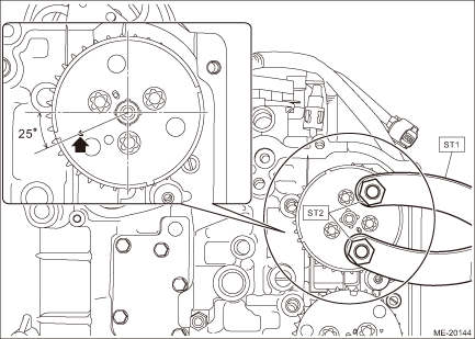
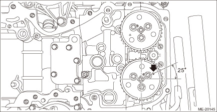
3. Using ST and by turning the intake cam sprocket LH, align the alignment marks to the positions as shown in the figure.
CAUTION:
• When the intake valve and exhaust valve lift at the same time, the valve heads contact each other and valve stem may bend. Do not turn the exhaust camshaft LH.
• Perform the operation carefully since the ST comes off easily.
| ST1 18355AA000 | PULLEY WRENCH |
| ST2 18334AA020 | PULLEY WRENCH PIN SET |
4. Using ST and by turning the crankshaft approximately 200° counterclockwise, align the alignment marks of crankshaft key to the positions as shown in the figure.
CAUTION:
Never turn clockwise because the valve and piston may contact. Clockwise turn is allowed only when adjusting the key position precisely, after turning the crankshaft counterclockwise to bring the key near the position as shown in the figure.
| ST 18252AA000 | CRANKSHAFT SOCKET |
5. Align the alignment mark of exhaust cam sprocket LH to the position shown in the figure.
CAUTION:
To prevent valve damage, turn the exhaust cam sprocket LH only within the range of zero-lift (in range where it can be turned lightly by hand).
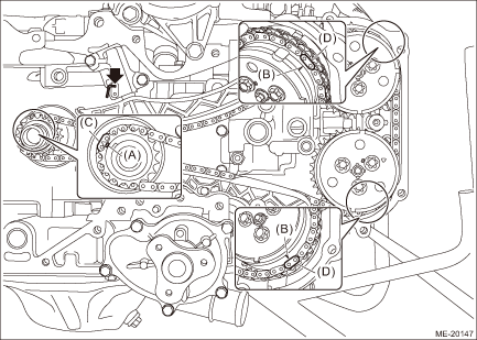
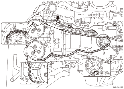
6. Install the timing chain LH and the timing chain guide LH.
(1) Match the timing chain mark (blue) to the alignment mark of the crank sprocket.
(2) Match the timing chain mark (pink) to the timing mark position of the intake cam sprocket LH.
(3) Match the timing chain mark (pink) to the timing mark position of the exhaust cam sprocket LH.
(4) Install timing chain guide LH.
Tightening torque:
6.4 N·m (0.7 kgf-m, 4.7 ft-lb)
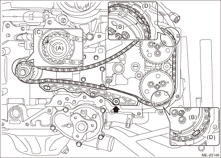
(A) | Alignment mark | (C) | Blue | (D) | Pink |
(B) | Timing mark |
7. Install O-rings to the cylinder block LH.
NOTE:
Use new O-rings.
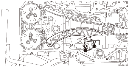
8. Install the chain tensioner lever LH (A) and chain tensioner LH.
Tightening torque:
6.4 N·m (0.7 kgf-m, 4.7 ft-lb)
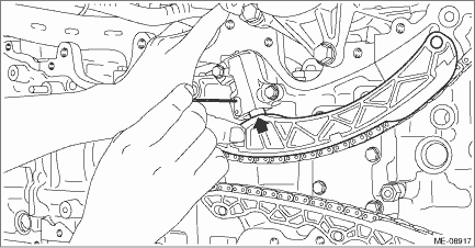
9. Pull out the stopper pin from the chain tensioner LH.
CAUTION:
Confirm the following before pulling out the stopper pin.
• Matching of the timing chain mark (blue) to the alignment mark of the crank sprocket.
• Matching of the timing chain mark (pink) to the timing mark position of the intake cam sprocket LH.
• Matching of the timing chain mark (pink) to the timing mark position of the exhaust cam sprocket LH.
NOTE:
If the stopper pin cannot be removed, lift the chain tension lever LH to remove as shown in the figure.
(A) | Alignment mark | (C) | Blue | (D) | Pink |
(B) | Timing mark |
10. Using the ST, turn the crankshaft clockwise, and make sure that there are no abnormal conditions.
CAUTION:
Always make sure to perform this confirmation.
| ST 18252AA000 | CRANKSHAFT SOCKET |
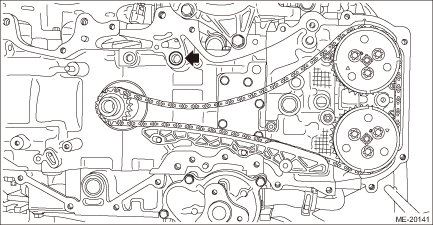
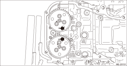
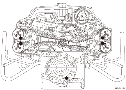
11. Using ST and by turning the crankshaft, align the alignment marks of crank sprocket, intake cam sprocket LH and exhaust cam sprocket LH to the positions as shown in the figure.
NOTE:
If the alignment marks are aligned to the positions as shown in the figure, the crankshaft key is located at six o’clock position.
| ST 18252AA000 | CRANKSHAFT SOCKET |

12. Install the timing chain RH. Timing Chain Assembly > INSTALLATION">
2. TIMING CHAIN RH
NOTE:
• Be careful that the foreign matter is not into or onto the assembled component during installation.
• Apply engine oil to all component parts of the timing chain.
1. Install timing chain LH. Timing Chain Assembly > INSTALLATION">
2. Prepare to attach the chain tensioner RH.
(1) Move the link plate (A) in the direction of arrow to press in the plunger (B).
(2) With a 2.5 mm (0.098 in) dia. stopper pin or a 2.5 mm dia. hex wrench inserted into the stopper pin hole, secure the plunger.
NOTE:
If the stopper pin hole on the link plate and the stopper pin hole on the chain tensioner are not aligned, check that the first notch of plunger rack (A) is engaged with the stopper tooth (B). If not engaged, retract the plunger a little so that the first notch of plunger rack (A) is engaged with the stopper tooth (B).
3. Make sure that the alignment marks of the crank sprocket, intake cam sprocket LH and exhaust cam sprocket LH are aligned to the positions as shown in the figure.
4. Align the alignment marks of intake cam sprocket RH and exhaust cam sprocket RH to the positions as shown in the figure.
CAUTION:
To prevent valve damage, turn the intake cam sprocket RH and exhaust cam sprocket RH only within the range of zero-lift (in range where it can be turned lightly by hand).
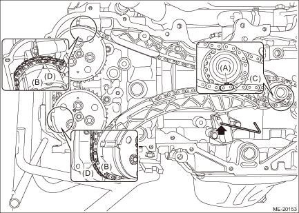
5. Install the timing chain RH and the timing chain guide RH.
(1) Match the timing chain mark (blue) to the alignment mark of the crank sprocket.
(2) Match the timing chain mark (pink) to the timing mark position of the intake cam sprocket RH.
(3) Match the timing chain mark (pink) to the timing mark position of the exhaust cam sprocket RH.
(4) Install the timing chain guide RH.
Tightening torque:
6.4 N·m (0.7 kgf-m, 4.7 ft-lb)
(A) | Alignment mark | (C) | Blue | (D) | Pink |
(B) | Timing mark |
6. Install the chain tensioner lever RH (A) and chain tensioner RH.
Tightening torque:
6.4 N·m (0.7 kgf-m, 4.7 ft-lb)
7. Pull out the stopper pin from the chain tensioner RH.
CAUTION:
Confirm the following before pulling out the stopper pin.
• Matching of the timing chain mark (blue) to the alignment mark of the crank sprocket.
• Matching of the timing chain mark (pink) to the timing mark position of the intake cam sprocket RH.
• Matching of the timing chain mark (pink) to the timing mark position of the exhaust cam sprocket RH.
(A) | Alignment mark | (C) | Blue | (D) | Pink |
(B) | Timing mark |
8. Make sure that the alignment marks of the cam sprocket and crank sprocket are aligned to the positions as shown in the figure.
9. Using the ST, turn the crankshaft clockwise, and make sure that there are no abnormal conditions.
CAUTION:
Always make sure to perform this confirmation.
| ST 18252AA000 | CRANKSHAFT SOCKET |
10. Install the chain cover. Chain Cover > INSTALLATION">
 Removal
MECHANICAL(H4DO) > Timing Chain AssemblyREMOVAL1. TIMING CHAIN RHNOTE:When replacing a single part, perform the work with the engine assembly installed to body.1. Remove the chain cover. Chain Cov ...
 V-belt
...
Other materials:
Terms
Packet write
This is a general term that describes
the process of writing data on-demand to
CD-R, etc., in the same way that data is
written to floppy or hard discs.
ID3 tag
This is a method of embedding trackrelated
information in an MP3 file. This
embedded information can incl ...
Roof tent
WARNING
Installing a roof tent on the Subaru Ascent increases the overall weight positioned
above the vehicle’s center of gravity, which can negatively influence handling,
braking efficiency, and rollover resistance. Under no circumstances should the Subaru
Ascent be driven if the total ...
Using aha application
1. When the top screen is displayed,
touch the station key.
Example of the main screen
2. Select the desired station from the list.
The selected station is displayed.
NOTE
The following operations are not
available on this system. Perform these
operations on the smartphone.
Add ...
