Subaru Crosstrek Service Manual: Removal
MECHANICAL(H4DO) > Timing Chain Assembly
REMOVAL
1. TIMING CHAIN RH
NOTE:
When replacing a single part, perform the work with the engine assembly installed to body.
1. Remove the chain cover. Chain Cover > REMOVAL">
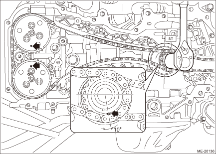
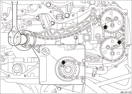
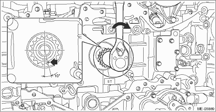
2. Using ST and by turning the crankshaft, align the alignment marks of crank sprocket, intake cam sprocket RH and exhaust cam sprocket RH to the positions as shown in the figure.
NOTE:
If the alignment marks are aligned to the positions as shown in the figure, the crankshaft key is located at six o’clock position.
| ST 18252AA000 | CRANKSHAFT SOCKET |
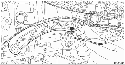
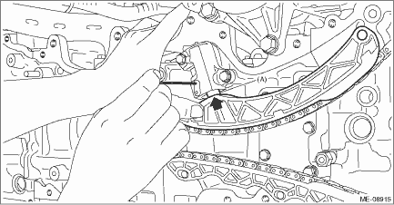
3. Push down the chain lever tensioner RH, and with a 2.5 mm (0.098 in) dia. stopper pin or a 2.5 mm dia. hex wrench inserted into the stopper pin hole in the chain tensioner RH, secure the plunger (A).
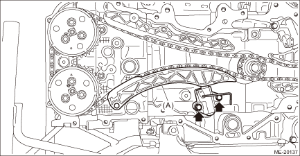
4. Remove the chain tensioner RH, and remove the chain tensioner lever RH (A).
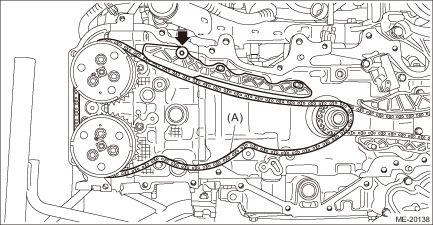
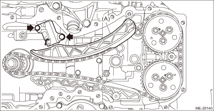
5. Remove the chain guide RH, and remove the timing chain RH (A).
CAUTION:
• If the timing chain RH is not installed, the intake camshaft RH and exhaust camshaft RH are kept at zero-lift position. All cams on the camshaft are not pressing down the roller rocker arm (intake valve and exhaust valve). (Under this condition, all valves remain unlifted.)
• Intake camshaft RH and exhaust camshaft RH can be independently rotated with the timing chain RH removed. When the intake valve and exhaust valve lift at the same time, the valve heads contact each other and valve stem may bend. Do not turn it to the outside of range of zero-lift (in range where it can be turned lightly by hand).
NOTE:
To avoid mixing with LH side, keep the removed part in order.
2. TIMING CHAIN LH
1. Remove the timing chain RH. Timing Chain Assembly > REMOVAL">
2. Using ST and by turning the crankshaft, align the alignment marks of crankshaft key, intake cam sprocket LH and exhaust cam sprocket LH to the positions as shown in the figure.
| ST 18252AA000 | CRANKSHAFT SOCKET |
3. Push down the chain lever tensioner LH, and with a 1.3 mm (0.05 in) dia. stopper pin or a 1.3 mm dia. hex wrench inserted into the stopper pin hole in the chain tensioner LH, secure the plunger (A).
4. Remove the chain tensioner LH, and remove the chain tensioner lever LH (A).
5. Remove the O-ring from the cylinder block LH.

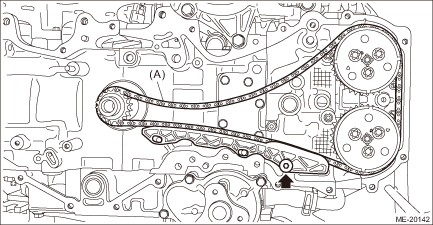
6. Remove the chain guide LH, and remove the timing chain LH (A).
CAUTION:
• If the timing chain LH is not installed, the exhaust camshaft LH is kept at zero-lift position. All cams on the exhaust camshaft LH are not pressing down the roller rocker arm (exhaust valve). (Under this condition, exhaust valves remain unlifted.)
• Intake camshaft LH is kept at lift position. All cams on the intake camshaft LH are pressing down the roller rocker arm (intake valve). (Under this condition, intake valves remain lifted.)
• Intake camshaft LH and exhaust camshaft RH can be independently rotated with the timing chain LH removed. When the exhaust camshaft LH is turned, the valve heads contact each other and valve stem may bend as described in above. Do not turn the exhaust camshaft LH to the outside of range of zero-lift (in range where it can be turned lightly by hand).
• #1 piston and #4 piston are located near TDC. If the intake camshaft LH is turned, the valve and the piston may contact and valve stem may bend. Do not turn the intake camshaft LH at this time.
NOTE:
To avoid mixing with RH side, keep the removed part in order.
7. Using ST and by turning the crankshaft approximately 200° clockwise, align the alignment marks of crank sprocket to the positions as shown in the figure.
CAUTION:
• This procedure is required to prevent the valve and piston contacting with each other, by moving the all pistons to the middle of the cylinders.
• Never turn counterclockwise because the valve and piston may contact. Counterclockwise turn is allowed only when adjusting precisely the alignment marks, after turning the crank sprocket alignment mark clockwise near the position as shown in the figure.
| ST 18252AA000 | CRANKSHAFT SOCKET |
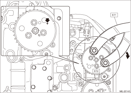
8. Using ST and by turning the intake cam sprocket LH approximately 180°, align the alignment marks of intake cam sprocket LH to the positions (zero-lift position) as shown in the figure.
CAUTION:
• After this work, when the intake valve and exhaust valve lift at the same time, the valve heads contact each other and valve stem may bend. Do not turn the intake camshaft LH and exhaust camshaft LH to the outside of range of zero-lift (in range where it can be turned lightly by hand).
• Perform the operation carefully since the ST comes off easily.
| ST1 18355AA000 | PULLEY WRENCH |
| ST2 18334AA020 | PULLEY WRENCH PIN SET |
 Inspection
MECHANICAL(H4DO) > Timing Chain AssemblyINSPECTION1. Check the timing chain, chain guide, chain tensioner lever and chain tensioner for deformation, cracks or other damages.2. Check the chain guide ...
 Installation
MECHANICAL(H4DO) > Timing Chain AssemblyINSTALLATION1. TIMING CHAIN LHNOTE:• Be careful that the foreign matter is not into or onto the assembled component during installation.• Apply e ...
Other materials:
Disassembly
EMISSION CONTROL (AUX. EMISSION CONTROL DEVICES)(H4DO) > Drain SeparatorDISASSEMBLY1. Disconnect the drain tube (A) from the leak check valve assembly.NOTE:Disconnect the quick connector as shown in the figure.2. Lift up the claw (B) of the drain separator and slide the drain separator in the dir ...
Current date and time setting
1. Perform the preparation steps according
to "Preparation for date setting" 3-
56.
2. Operate the "
" or "
" switch to
select the "Time/Date" item. Then push
the
button.
3. Select the item to set by operating the
"
" or "
" switch. Then push the
button.
...
Cargo area cover
The Subaru Ascent cargo area cover is designed to shield stored items from direct
sunlight and provide additional privacy. It can also be removed easily when transporting
larger cargo.
Using the cover
To extend the cargo cover in the Subaru Ascent, pull it outward from its housing
and se ...
