Subaru Crosstrek Service Manual: Removal
SECURITY AND LOCKS > Steering Lock CM
REMOVAL
CAUTION:
• Before handling the airbag system components, refer to “CAUTION” of “General Description” in “AIRBAG SYSTEM”. General Description > CAUTION">
• Do not allow harness and connectors to interfere or get tangled up with other parts.
• If the steering wheel and steering angle sensor (steering roll connector) are removed, perform “VSC(VDC) Centering Mode” of the VDC. VDC Control Module and Hydraulic Control Unit (VDCCM&H/U) > ADJUSTMENT">
1. Disconnect the ground cable from battery and wait for at least 60 seconds before starting work. NOTE">
2. Remove the cover assembly - instrument panel LWR driver. Instrument Panel Lower Cover > REMOVAL">
3. Remove the knee airbag module. Knee Airbag Module > REMOVAL">
4. Remove the universal joint assembly - steering. Universal Joint > REMOVAL">
5. Remove the column assembly - steering. Steering Column > REMOVAL">
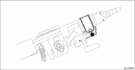
6. Remove the steering lock CM.
(1) Secure the column assembly - steering in a vise.
(2) Use the reverse tap or drill to remove the set bolt and remove the steering lock CM.
CAUTION:
Do not apply any impact to the set bolt by a chisel or punch.
 Inspection
SECURITY AND LOCKS > Steering Lock CMINSPECTION1. Check if the steering lock is released when you start the engine using the push button ignition switch.2. If the system does not operate normally a ...
 Installation
SECURITY AND LOCKS > Steering Lock CMINSTALLATIONCAUTION:• When the control module related to immobilizer has been replaced, be sure to perform the registration of immobilizer system. For det ...
Other materials:
Preparation tool
DRIVE SHAFT SYSTEM > General DescriptionPREPARATION TOOL1. SPECIAL TOOLILLUSTRATIONPART NO.DESCRIPTIONREMARKS20099PA010INSTALLER & REMOVER• Used for replacing the rear bushing of rear axle housing.• Used together with BUSHING REMOVER (20099FG000).20099FG000BUSHING REMOVER• U ...
Installation
CONTINUOUSLY VARIABLE TRANSMISSION(TR580) > Transmission HarnessINSTALLATION1. INHIBITOR HARNESSInstall in the reverse order of removal.NOTE:Install the transmission ground terminal in the direction within the range of approx. 30° (A).Tightening torque:T1: 7 N·m (0.7 kgf-m, 3.7 ...
Operation
AUTO HEADLIGHT BEAM LEVELER SYSTEM (DIAGNOSTICS) > Read Current DataOPERATION1. On «Start» display, select «Diagnosis».2. On «Vehicle selection» display, input the target vehicle information and select «Confirmed».3. On «Main Menu» display, select «Each System».4. On «Select System» ...
