Subaru Crosstrek Service Manual: Installation
CONTINUOUSLY VARIABLE TRANSMISSION(TR580) > Transmission Harness
INSTALLATION
1. INHIBITOR HARNESS
Install in the reverse order of removal.
NOTE:
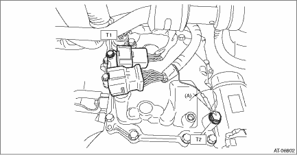
Install the transmission ground terminal in the direction within the range of approx. 30° (A).
Tightening torque:
T1: 7 N·m (0.7 kgf-m, 3.7 ft-lb)
T2: 14 N·m (1.4 kgf-m, 10.3 ft-lb)
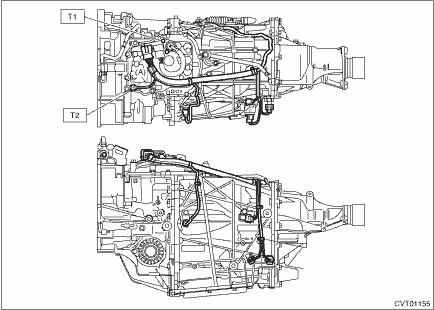
2. TRANSMISSION HARNESS
1. Clean the mating surface of valve cover and transmission side.
CAUTION:
When cleaning the mating surface of the transmission side, be careful not to allow any dust, foreign matter and used liquid gasket to enter the transmission.
2. Check the control valve body for dust and other foreign matter.
3. Install the O-ring to the transmission harness.
NOTE:
• Use new O-rings.
• Apply CVTF to the O-rings.
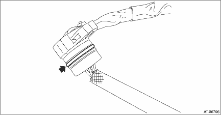
4. Install the transmission harness to the valve cover.
Tightening torque:
7 N·m (0.7 kgf-m, 5.2 ft-lb)
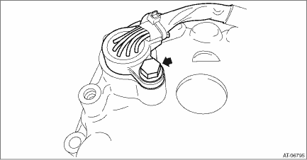
5. Install the gasket to the transmission.
NOTE:
Use a new gasket.
6. Apply liquid gasket to the oval hole of gasket.
Liquid gasket:
THREE BOND 1215B or equivalent
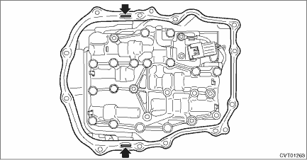
7. Connect the transmission harness connector to the control valve body, and install the valve cover.
CAUTION:
Be careful not to catch the sheet of the ST.
Tightening torque:
8 N·m (0.8 kgf-m, 5.9 ft-lb)
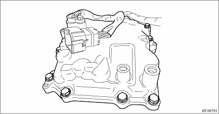
8. Remove the ST (SHEET SPECIAL TOOL).
9. Install the transmission harness connector to the harness stay.
10. Install the transmission harness stay and transmission ground terminal.
NOTE:
Install the transmission ground terminal in the direction within the range of approx. 30° (A).
Tightening torque:
T1: 7 N·m (0.7 kgf-m, 5.2 ft-lb)
T2: 14 N·m (1.4 kgf-m, 10.3 ft-lb)
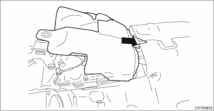
11. Insert the transmission case cover (small) between the transmission case cover (large) and the transmission to install.
Tightening torque:
8 N·m (0.8 kgf-m, 5.9 ft-lb)
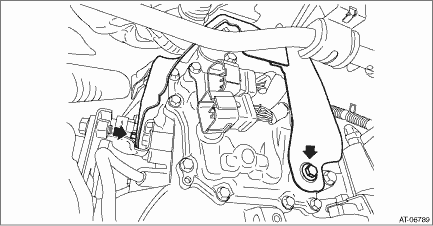
12. Install the pitching stopper bracket and transmission radio ground cord.
CAUTION:
Be careful not to deform or damage the terminal of transmission radio ground cord.
Tightening torque:
41 N·m (4.2 kgf-m, 30.2 ft-lb)

13. Install the air breather hose to the pitching stopper bracket.
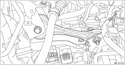
14. Install the pitching stopper.
Tightening torque:
T1: 50 N·m (5.1 kgf-m, 36.9 ft-lb)
T2: 58 N·m (5.9 kgf-m, 42.8 ft-lb)
15. Connect the following harness connectors.
• Transmission harness connectors
• Inhibitor harness connector
• Transmission radio ground terminal
Tightening torque:
13 N·m (1.3 kgf-m, 9.6 ft-lb)
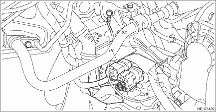
(A) | Transmission harness connectors |
(B) | Inhibitor harness connector |
(C) | Transmission radio ground terminal |
16. Install the air intake boot assembly. Air Intake Boot > INSTALLATION">
17. Adjust the CVTF level. CVTF > ADJUSTMENT">
 Removal
CONTINUOUSLY VARIABLE TRANSMISSION(TR580) > Transmission HarnessREMOVAL1. INHIBITOR HARNESS1. Remove the transmission from the vehicle. Automatic Transmission Assembly > REMOVAL">2. Rem ...
Other materials:
Caution
ENTERTAINMENT > General DescriptionCAUTION• Before disassembling or reassembling parts, always disconnect the battery ground cable from battery. When replacing the audio, control module and other parts provided with memory functions, record the memory contents before disconnecting the batte ...
Operation
INSTRUMENTATION/DRIVER INFO > Combination Meter SystemOPERATION1. SELF-DIAGNOSIS DISPLAY MODEThe self-diagnosis (checking of each meter, warning light, indicator light, illumination, LCD/TFT) of combination meter can be performed in the following procedure.1. ProcedureCAUTION:Perform the steps de ...
Select lever
Select lever positions
Select lever button
With the brake pedal depressed,
shift
while pressing the select lever button in.
Shift while pressing the select
lever
button in.
Shift without pressing the
select lever
button.
The select lever has four positions, "P",
"R", "N", ...

