Subaru Crosstrek Service Manual: Removal
POWER ASSISTED SYSTEM (POWER STEERING) > Steering Column
REMOVAL
CAUTION:
Before handling the airbag system components, always refer to “CAUTION” of “General Description” in “AIRBAG SYSTEM”. General Description > CAUTION">
1. Disconnect the ground cable from battery and wait for at least 60 seconds before starting work. NOTE">
2. Remove the driver’s airbag module. Driver’s Airbag Module > REMOVAL">
3. Remove the steering wheel. Steering Wheel > REMOVAL">
4. Remove the cover assembly - instrument panel LWR driver. Instrument Panel Lower Cover > REMOVAL">
5. Remove the knee airbag module. Knee Airbag Module > REMOVAL">
6. Remove the cover assembly - column.
(1) Release the screws and claws.
(2) Remove the cap - key cylinder (a). (Model with keyless access with push button start)
(3) Remove the cover assembly - column UPR and the cover assembly - column LWR.
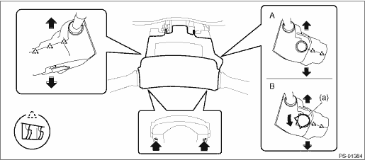
A | Model without keyless access with push button start | B | Model with keyless access with push button start |
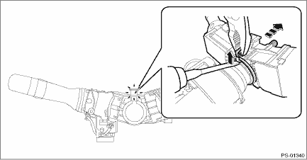
7. Remove the switch assembly - combination.
(1) Disconnect the connector, and loosen the clamp to release the claws.
(2) Pull out the switch assembly - combination from the column assembly - steering.
8. Remove all connectors from the column assembly - steering.
9. Remove the universal joint assembly - steering. Universal Joint > REMOVAL">
CAUTION:
To prevent damage to the universal joint assembly - steering and improper steering effort, make sure to remove the universal joint assembly - steering.
10. Remove the two nuts under the beam COMPL - steering securing the column assembly - steering.
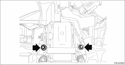
11. Pull out the column assembly - steering from the hole on toe board.
CAUTION:
Do not loosen the tilt lever when the column assembly - steering is not secured to the vehicle.
12. Remove the ignition key lock from the column assembly - steering. Ignition Key Lock > REPLACEMENT">
 Inspection
POWER ASSISTED SYSTEM (POWER STEERING) > Steering ColumnINSPECTION1. UNIT INSPECTIONCheck the following items, and if there is anything out of standard value, it is considered to be damaged. If so, ...
 Installation
POWER ASSISTED SYSTEM (POWER STEERING) > Steering ColumnINSTALLATIONCAUTION:If the steering wheel and steering angle sensor are removed, perform the following VDC setting mode.– Model without Ey ...
Other materials:
Removal
SECURITY AND LOCKS > Rear Door Latch and Door Lock Actuator AssemblyREMOVAL1. Disconnect the ground cable from battery. NOTE">2. Remove the trim panel - rear door. Door Trim > REMOVAL">3. Remove the sealing cover - rear door. Rear Sealing Cover > REMOVAL">4. Remov ...
Dtc p0604 internal control module random access memory (ram) error
CONTINUOUSLY VARIABLE TRANSMISSION (DIAGNOSTICS) > Diagnostic Procedure with Diagnostic Trouble Code (DTC)DTC P0604 INTERNAL CONTROL MODULE RANDOM ACCESS MEMORY (RAM) ERRORDTC DETECTING CONDITION:Detected when two consecutive driving cycles with fault occur.TROUBLE SYMPTOM:TCM RAM malfunctionSTEP ...
Inspection
MANUAL TRANSMISSION AND DIFFERENTIAL(5MT) > Transmission Mounting SystemINSPECTIONCheck the following; repair or replace the faulty parts.1. PITCHING STOPPERCheck the pitching stopper for bends or damage. Check that the rubber is not stiff, cracked or otherwise damaged.2. CROSSMEMBER AND CUSHION ...
